A locking mechanism and a forging die using the locking mechanism

A locking mechanism and die technology, used in forging/pressing/hammer devices, forging/pressing/hammering machinery, manufacturing tools, etc. problem, to achieve the effect of reliable locking state, automatic locking, and avoiding dependence on external force

Active Publication Date: 2016-09-14
HENAN PINGGAO ELECTRIC +2
View PDF5 Cites 1 Cited by
  • Summary
  • Abstract
  • Description
  • Claims
  • Application Information

AI Technical Summary

Problems solved by technology

[0003] Molds with mold locking requirements are often used in the injection molding process. The locking force is generally provided by the injection molding machine itself or an additional special locking mechanism is used. The locking form is generally hydraulic locking, and the hydraulic locking structure is used. At the same time of large locking force, it is easy to realize the automation of locking and facilitate automatic production. However, it is not suitable to use hydraulic structure for locking in hot forging dies, because the working environment of forging is generally poor, with large dust and high temperature. The sealing performance of the hydraulically locked pipeline will deteriorate, which will lead to a decrease in the locking force and make the locking force insufficient

Method used


Image

  • A locking mechanism and a forging die using the locking mechanism
  • A locking mechanism and a forging die using the locking mechanism
  • A locking mechanism and a forging die using the locking mechanism

Examples


Embodiment Construction

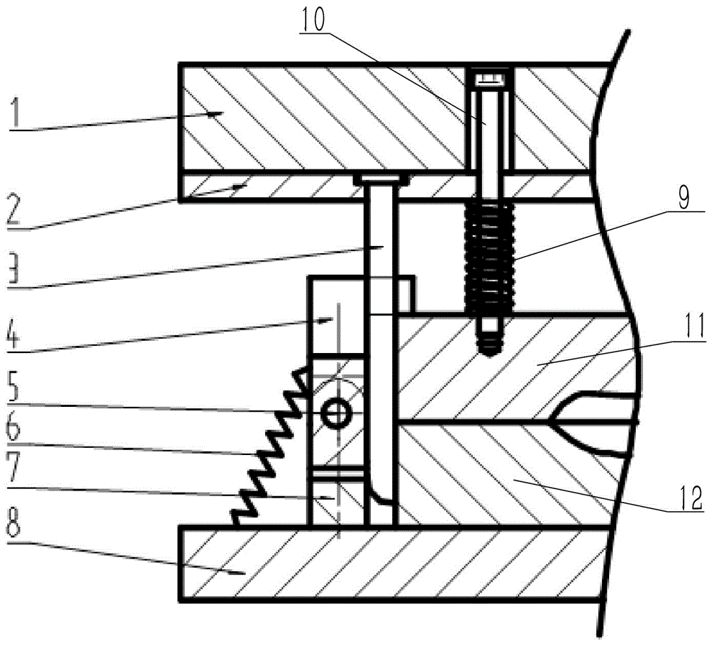
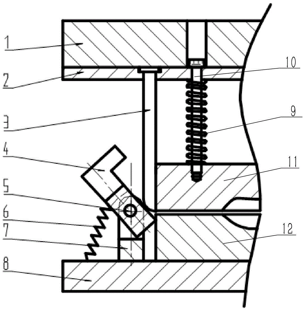
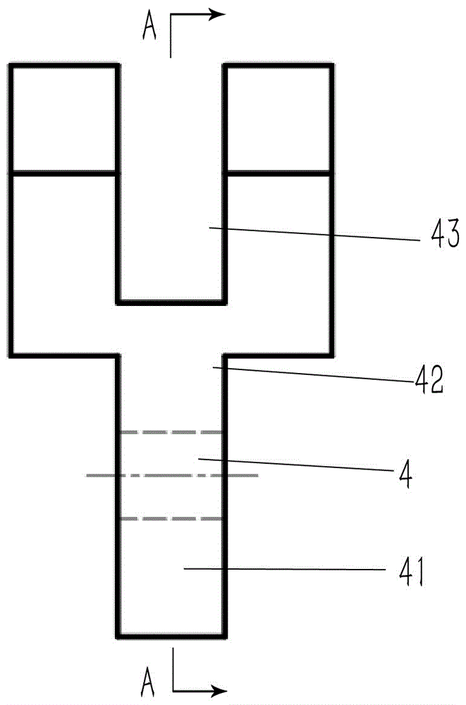
[0024] The embodiment of forging die among the present invention: as Figure 1 to Figure 6 As shown, the forging device is mainly composed of an upper mold, a lower mold and a locking mechanism, wherein the upper mold is composed of an upper template 1, a pressing plate 2, a guide rod 10 and an upper mold body 11, and the upper mold body 11 passes through the guide rod 10 The detachment is assembled under the pressure plate 2, and the outer circumference of the guide rod 10 is equipped with a top pressure spring 9 installed between the pressure plate 2 and the upper mold body 11; The edge portion of the upper body is vertically provided with a hinged seat spaced apart from the lower mold body 12, and the gap between the hinged seat and the lower mold body 12 is a downwardly recessed guiding channel. The locking mechanism includes a turning member 4 hinged on the hinge seat 7 through a hinge shaft 5, a push rod 3 fixed on the pressing plate 2, and a return spring 6 connected be...


PUM


Abstract

The invention discloses a locking mechanism and a forging die using the locking mechanism. The ejector rod of the locking mechanism is fixed on the upper mold, and the turning part is hinged on the lower die, and the turning is realized through the cooperation of the lower swing arm of the turning part and the bottom end of the ejector rod, and the upper swing arm of the turning part can realize the rotation of the upper die. lock, so that during the forging process, with the relative pressing of the upper and lower dies, the ejector rod on the upper die will press down on the press-fitting part on the lower swing arm, so that the upper swing arm of the flip part Flip upward until the upper mold is completely pressed on the lower mold, the claws on the upper swing arm of the overturned part will be fastened on the edge of the upper mold to lock the upper mold on the lower mold, so as to realize the upper and lower molds. Therefore, this locking method not only makes the locking state between the upper and lower molds more reliable, but also drives the action of the locking mechanism through the relative pressing force of the upper and lower molds, realizing the pressing Automatic locking during the process.

Description

technical field [0001] The invention relates to a locking mechanism and a forging die using the locking mechanism. Background technique [0002] At present, when cold forging or hot forging of metal materials is carried out, the forging and pressing of the workpiece will be realized through the relative pressing of the upper and lower dies. After the upper die falls, the upper and lower dies need to be locked. Closed together to achieve the subsequent molding process of the workpiece, mold locking is a requirement for the molding mold structure when there is a certain or greater pressure in the cavity during the plastic molding process. [0003] Molds with mold locking requirements are often used in the injection molding process. The locking force is generally provided by the injection molding machine itself or an additional special locking mechanism is used. The locking form is generally hydraulic locking, and the hydraulic locking structure is used. At the same time of la...

Claims


Application Information

Patent Timeline
Patent Type & Authority Patents(China)
IPC IPC(8): B21J13/02B21J13/08
CPCB21J13/02
Inventor 何洲赵飞秦冬雁齐向前王海军杨俊朋
Owner HENAN PINGGAO ELECTRIC
Why Eureka
Try Eureka