Correcting and positioning device for through-flow blade processing equipment

A technology of processing equipment and cross-flow fan blades, which is applied in the field of calibration and positioning devices, can solve the problems affecting the positioning accuracy of parts, welding effect, and deformation of parts under force, and achieves the effect of accurately correcting positioning and improving welding accuracy.

Inactive Publication Date: 2015-02-04
NINGBO FATO AUTOMATION TECH
View PDF8 Cites 3 Cited by
  • Summary
  • Abstract
  • Description
  • Claims
  • Application Information

AI Technical Summary

Problems solved by technology

[0004] However, there are still some deficiencies in the cross-flow fan blade correction and positioning device in the existing cross-flow fan blade processing equipment: since the cross-flow fan blade is a plastic product, when the steel shaft wheel, the middle section of the impeller or the rubber wheel clamp It is easy to cause these parts to be deformed by force, and the correction and positioning operation of each part of the cross-flow fan requires the reference positions on the surface of the parts to achieve high-precision matching, which will inevitably affect the final part positioning accuracy and welding effect

Method used


Image

  • Correcting and positioning device for through-flow blade processing equipment
  • Correcting and positioning device for through-flow blade processing equipment
  • Correcting and positioning device for through-flow blade processing equipment

Examples


Embodiment Construction

[0014] The present invention will be described in further detail below in conjunction with the embodiments of the drawings.

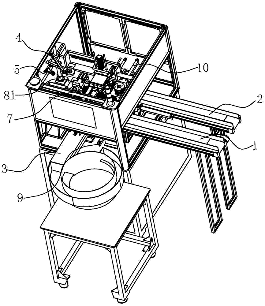
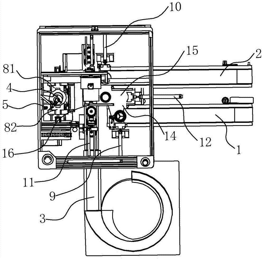
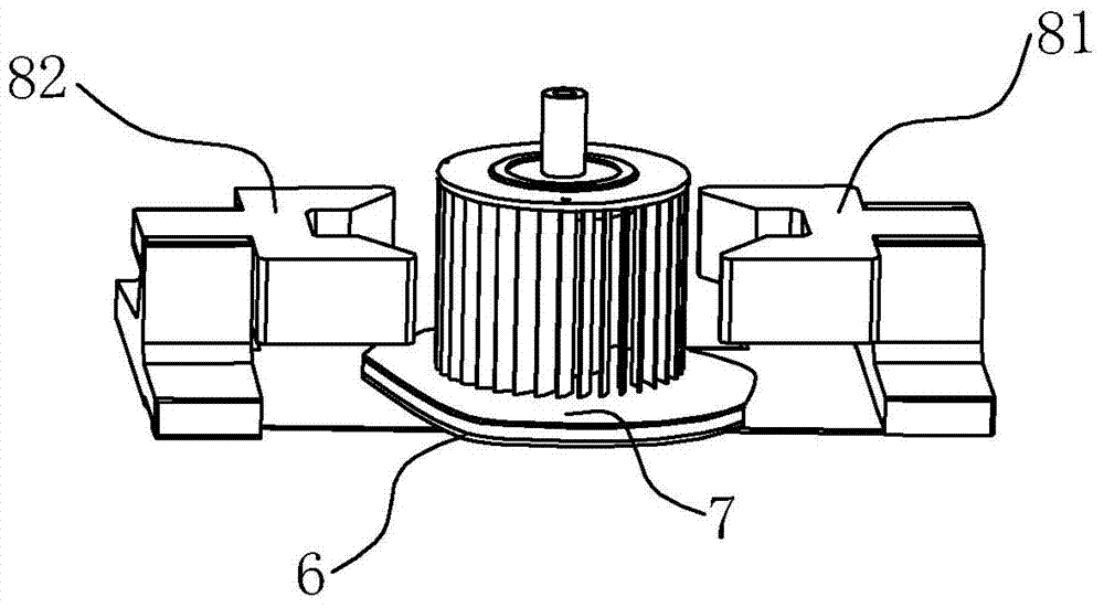
[0015] Such as figure 1 with figure 2 As shown, the correction positioning device of the cross-flow fan blade processing equipment in the embodiment of the present invention is respectively connected with the first linear conveying track 1, the second linear conveying track 2 and the third linear conveying track 3 of the input component. The device includes a swingable cylinder jaw 4, a CMOS image acquisition device 5 connected to a controller, a rotatable positioning plate 6, a rotating positioning plate 7, and a movable first positioning jaw 81 and a second positioning jaw 82, The cylinder jaws 4 and the CMOS image acquisition device 5 are both arranged above the rotary positioning plate 7, the rotary positioning plate 7 is arranged on the positioning plate 6, and the opening of the first positioning jaw 81 and the opening of the second positioning jaw 8...


PUM


Abstract

The invention relates to a correcting and positioning device for through-flow blade processing equipment. The correcting and positioning device is respectively connected with a first linear conveying rail, a second linear conveying rail and a third linear conveying rail of an input component, and comprises an air cylinder clamping jaw, CMOS image collecting equipment, a positioning flat plate, a rotating positioning disc, a first positioning clamping jaw and a second positioning clamping jaw, wherein the air cylinder clamping jaw can swing, the CMOS image collecting equipment is connected with a controller, the positioning flat plate can rotate, the first positioning clamping jaw and the second positioning clamping jaw can move, the air cylinder clamping jaw and the CMOS image collecting equipment are respectively arranged above the rotating positioning disc, the rotating positioning disc is arranged on the positioning flat plate, an opening of the first positioning clamping jaw is in opposite arrangement to an opening of the second positioning clamping jaw, and the positioning flat plate is arranged in the middle position between the two openings. The CMOS image collecting equipment collects the surface information of a component arranged on the rotating positioning disc and sends the surface information to the controller for storage, and then, the angle of a subsequent component arranged on the rotating positioning disc is regulated to be respectively identical to the angle of a former component stored in the controller, so that the fast and precise correcting and positioning of a through-flow blade is realized.

Description

Technical field [0001] The invention relates to the field of cross-flow fan blades, and in particular to a correction and positioning device for cross-flow fan blade processing equipment. Background technique [0002] The cross flow fan is the main part responsible for air supply in the air conditioner. Under normal circumstances, the cross-flow fan blades are welded by steel shaft wheel, impeller middle section and rubber wheel. With the development of digitization, automation, computer and mechanical design technology, automatic processing equipment for cross flow blades came into being. The automatic processing equipment of cross flow blades mainly includes a controller, a feeding device, a cross flow blade correction positioning device, an ultrasonic welding device and a discharge device. In the welding process of cross-flow fan products, the correct positioning of the steel shaft wheel, the middle section of the impeller and the rubber wheel of the cross-flow fan is very i...

Claims


Application Information

Patent Timeline
IPC IPC(8): B25B11/00B29C65/08
CPCB25B11/00B29C65/08
Inventor 施红文施文灿施展魏黎明
Owner NINGBO FATO AUTOMATION TECH
Why Eureka
Try Eureka