A vehicle and its active lateral stabilizing device

A technology of a lateral stabilizer and a stabilizer bar, which is applied to vehicle components, transportation and packaging, interconnection systems, etc., can solve the problems of large roll angle, increase the torsional stiffness of the stabilizer bar, increase the cost, etc., and reduce the vibration of the roll angle. , Provide the effect of ride smoothness and large anti-rolling moment

Active Publication Date: 2017-07-28
ZHENGZHOU YUTONG BUS CO LTD
View PDF9 Cites 0 Cited by
  • Summary
  • Abstract
  • Description
  • Claims
  • Application Information

AI Technical Summary

Problems solved by technology

The problem with this existing lateral stabilizer is that when the vehicle is turning and rolls at a large angle, in order to resist the roll, the torsional stiffness of the stabilizer bar needs to be designed to be larger, and in order to improve the ride comfort and stability of the vehicle. Passability, when the vehicle is walking on an uneven road, the inclination angle of the vehicle is small. At this time, it is not expected that the stabilizer bar will produce a large roll stiffness. Therefore, the torsional stiffness of the stabilizer bar needs to be designed to be appropriately small. For the passive stabilizer bar structure, the above contradictions are difficult to coordinate and unify, that is to say, even if the vehicle has a small roll angle, the stabilizer bar will also increase the torsional stiffness of the vehicle, making the vehicle produce a greater Roll angle vibration affects ride comfort; in addition, the anti-tilt moment that the stabilizer bar can generate is determined by the roll angle of the vehicle body (which can be equivalently converted into the deformation angle of the stabilizer bar) and the torsional stiffness of the stabilizer bar It is determined that in order to obtain a large enough anti-rolling moment when the vehicle is at a large inclination angle, the torsional stiffness of the stabilizer bar must be designed to be very large, which will increase the cost on the one hand, and affect the unevenness of the vehicle on the other hand. Ride smoothness during road driving, so this problem cannot be solved simply by increasing the torsional stiffness of the stabilizer bar

Method used


Image

  • A vehicle and its active lateral stabilizing device
  • A vehicle and its active lateral stabilizing device

Examples


Embodiment Construction

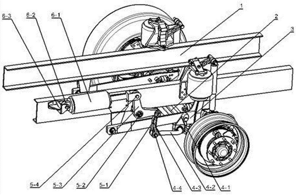
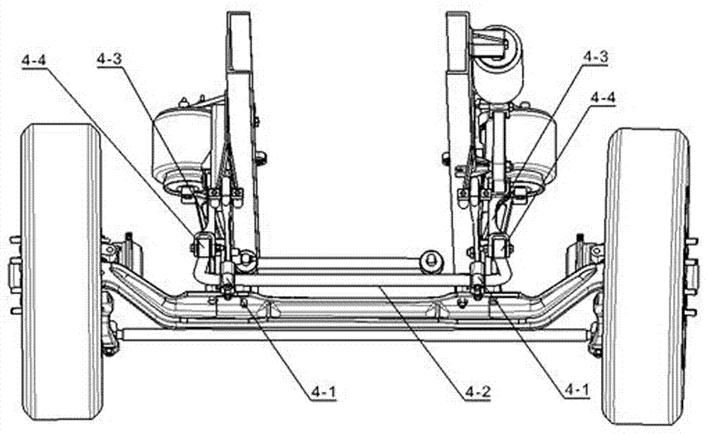
[0015] An example of a vehicle such as Figure 1~2 Shown: including body 1, suspension 3 and active lateral stabilization device arranged between the body and suspension, axle 2 is arranged at the lower end of suspension 3, and active lateral stabilization device includes a lateral stabilizer bar arranged on suspension 3 4-2 and the drive devices respectively arranged at both ends of the stabilizer bar. The stabilizer bar is a complete U-shaped bar structure. Each drive device includes a power output piece. The drive device is connected with the corresponding end of the stabilizer bar to drive The torsion power output end of the stabilizer bar. The two driving devices at both ends of the stabilizer bar have the same structure. Only one of the driving devices will be described in detail. The driving device includes a power output crank arm whose rotation axis extends laterally. The power input crank arm is fixed on the top, and the power output crank arm and the power input cra...


PUM


Abstract

The invention relates to a vehicle and an active transverse stabilizing device thereof. The active transverse stabilizing device comprises a transverse stabilizing rod and a driving device, wherein the transverse stabilizing rod is used for being arranged on a corresponding suspension, and the driving device is arranged at at least one end of the transverse stabilizing rod; the driving device comprises a power output member which is used for being arranged on a corresponding vehicle body, and the driving device is provided with a power output end which is in transmission connection with a corresponding end of the transverse stabilizing rod so as to drive the transverse stabilizing rod to twist. The invention provides the active transverse stabilizing device, which can actively adjust the rolling resisting moment of the transverse stabilizing rod to the vehicle body, and the vehicle employing the active transverse stabilizing device.

Description

technical field [0001] The invention relates to a vehicle and an active lateral stabilizing device thereof. Background technique [0002] According to statistics, traffic accidents caused by passenger car rollover account for as high as 30% of all accidents, and the improvement of vehicle roll stability and anti-roll performance can effectively avoid rollover accidents and improve vehicle handling stability and ride comfort. In the prior art, a stabilizer bar is mainly used to improve the roll stability of the vehicle, such as "a front air suspension system for a large bus" disclosed in Chinese patent CN201659862U. The suspension system includes a vehicle body and a suspension. A transverse stabilizer bar is arranged, and the two ends of the transverse stabilizer bar are respectively connected with the left and right sides of the vehicle body. When the vehicle turns left, the body tilts to the right, the right side of the suspension is under pressure, and the left side is ...

Claims


Application Information

Patent Timeline
Patent Type & Authority Patents(China)
IPC IPC(8): B60G21/055
Inventor 郭耀华汤望贾针海辰光秦涛刘万备严斌
Owner ZHENGZHOU YUTONG BUS CO LTD
Why Eureka
Try Eureka