
Peripheral barrier-free clamp for palletizing robot

A palletizing robot and gripper technology, which is applied to the parts and packaging of strapping machines, can solve the problems of inconvenience, cost increase, and production efficiency reduction, and achieve the effects of convenient use, avoiding investment, and simple structure

Active Publication Date: 2015-02-04
珠海林顺机电有限公司
View PDF7 Cites 2 Cited by
  • Summary
  • Abstract
  • Description
  • Claims
  • Application Information

AI Technical Summary

Problems solved by technology

However, the above-mentioned first method needs to invest a lot of labor, which will increase the labor cost, is not conducive to the development of the enterprise, and increases the labor intensity of the staff. However, when the staff is in a fatigued state, they will not be able to support them well. It is obviously not worth the candle to cause the cargo packaging box to fall; although the second method does not require manual support, since the support strips are set around the cargo board, it will cause inconvenience in bundling during the bundling process after the cargo is stacked. , or keep the support bar, the binding rope is bound around the support bar; or remove the support bar
If the support strips are kept, the number of support strips required will increase greatly, and the cost will increase accordingly, and the transportation cost will be increased during transportation, and it will also be inconvenient when unloading after arriving at the destination
If the support strips are removed and then bundled, it is very likely that during the process of removing the support strips, the cargo packaging boxes on the entire cargo board will be dumped and need to be re-stacked, and even the goods in the packaging boxes will be damaged, which is difficult to guarantee The integrity of the goods will increase the stacking time and reduce the production efficiency

Method used

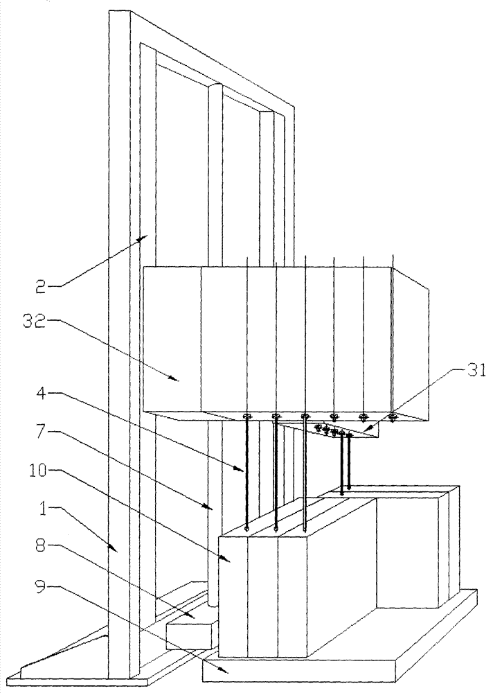
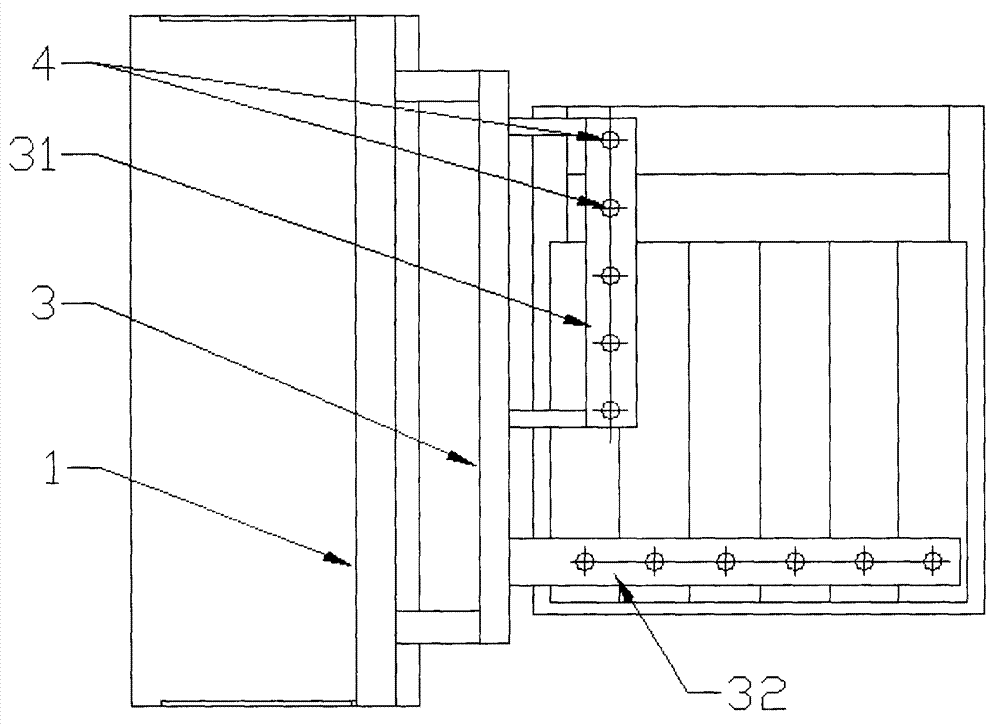
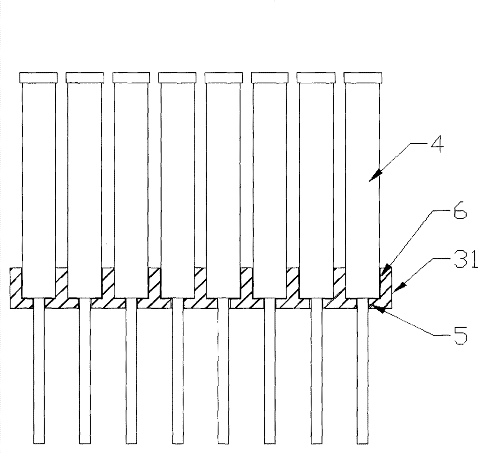

Image

  • Peripheral barrier-free clamp for palletizing robot
  • Peripheral barrier-free clamp for palletizing robot
  • Peripheral barrier-free clamp for palletizing robot

Examples


Embodiment Construction

[0019] Such as Figure 1 to Figure 3 As shown, in this embodiment, the present invention includes a frame 1, on which a guide rail 2 is arranged, on which a cylinder assembly frame 3 is slidably fitted, and the cylinder assembly frame 3 Driven by the power device arranged on the frame 1 to move up and down on the guide rail 2, several vertically arranged cylinders 4 are arranged in the cylinder assembly frame 3, and the output of several cylinders 4 Shaft facing down. The area of ​​the orthographic projection of the cylinder pallet 3 is equivalent to the area of ​​the peripheral cargo board. Universal wheels are arranged on the bottom plate of the frame 1 , and the holder can be moved in the workshop through the universal wheels. The power device can have the following two structures.

[0020] 1. The power device is a screw rod 7 arranged on the frame 1, the screw rod 7 passes through the threaded hole arranged on the cylinder assembly frame 3, and is set on the frame 1 Th...


PUM


Abstract

The invention aims to provide a peripheral barrier-free clamp for a palletizing robot, which is simple in structure, is convenient to use and has high efficiency. The peripheral barrier-free clamp comprises a frame (1), wherein a guide rail (2) is arranged on the frame (1); the guide rail (2) is in sliding fit with a cylinder pallet (3); the cylinder pallet (3) is driven to move up and down on the guide rail (2) through a power device arranged on the frame (1); a plurality of vertical cylinders (4) are arranged in the cylinder pallet (3); output shafts of the cylinders (4) are arranged downwardly. The peripheral barrier-free clamp is applied to the technical field of palletizing robots.

Description

technical field [0001] The invention relates to a clamping device, in particular to a peripheral barrier-free clamper for a palletizing robot. Background technique [0002] In the production workshop, after the goods are assembled and tested, they need to be packaged, and the packaged goods are placed on the cargo board, and the goods are bound and fixed by ropes, strapping machines, etc., and finally the cargo board and the goods are packed together. car transport. For box-packed goods, such as liquid crystal display packaging, since the surface of the box with the largest area has the largest area ratio to the surface with the smallest area, when the smallest surface is placed on the cargo board as a support surface, it is necessary to stack more. boxes to complete the loading of a pallet. In the process of stacking the packaging boxes, since the supporting surface area of ​​the packaging box is small and its height is high, if no support is provided, the packaging box i...

Claims


Application Information

Patent Timeline
Patent Type & Authority Applications(China)
IPC IPC(8): B65B13/20
CPCB65B13/20B65B35/50
Inventor 罗仲孚
Owner 珠海林顺机电有限公司
Learn More