
Intelligent well top part packer

A technology for packers and smart wells, which is applied in sealing/isolation, wellbore/well components, earthwork drilling and production, etc. It can solve the problems of low pressure resistance level, smaller inner diameter of packer, and shortened design length, etc. problems, to achieve the effect of increasing the inner diameter, large self-locking force and shortening the length

Active Publication Date: 2015-02-04
DONGYING FLUID SCI & TECH
View PDF6 Cites 9 Cited by
  • Summary
  • Abstract
  • Description
  • Claims
  • Application Information

AI Technical Summary

Problems solved by technology

[0002] The intelligent completion technology realizes the production control of the downhole oil and gas layer by the ground through the umbilical cable. The structure of the existing top packer is to reduce the internal diameter, and the vertical umbilical cable crossing hole is designed on the wall of the packer center pipe , has played a role in the intelligent completion technology of oil production, but it also has the following shortcomings or deficiencies: ①Because the top packer has to pass through the pipe cable, the inner diameter of the packer becomes smaller, and subsequent operation tools are difficult to run into ; ②If the internal diameter is increased, the radial wall thickness of the packer will decrease, and the design of the self-locking mechanism is difficult, which cannot provide a large self-locking force; ③In order to reduce the difficulty of umbilical cable penetration, the packer body The design length should also be shortened as much as possible; ④The pressure resistance level is low. When the pressure under the rubber tube is too high, it may cause the packer to unseal. In an environment with a high pressure level, it is necessary to install anchor tiles to ensure the safety of the tool

Method used


Image

  • Intelligent well top part packer
  • Intelligent well top part packer

Examples


Embodiment Construction

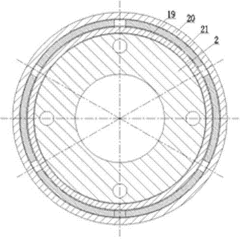
[0015] refer to Figure 1-Figure 2 , an intelligent well top packer, including an upper joint 1, a center pipe 2, a slip cover 3, a pressure spring 4, slips 5, a cone 7, an adjustment ring 8, a rubber tube 9, a piston 10, and a suspension ring 13 , Pressure-isolated sleeve 16, limit ring 17, unblocking pin 18, limit sleeve 19, locking sleeve 20, lock ring 21, spring 22, pressure cap 23, lower joint 24. The upper part of the central pipe 2 is connected with the upper joint 1, and the lower part is connected with the lower joint 24. The outer part of the central pipe 2 is sequentially connected with a slip cover 3, a pressure spring 4, a slip 5, a cone 7, an adjustment ring 8, a glue Barrel 9, piston 10, locking sleeve 20 and pressure cap 23, piston 10 is lowered and pressure cap 23 is installed with pressure isolation sleeve 16, limit sleeve 19, lock ring 21 and spring 22, piston 10, pressure isolation sleeve 16 Suspension ring 13 is installed, under the pressure isolation sle...


PUM


Abstract

The invention provides an intelligent well top part packer, comprising an upper joint, a center pipe, a slip cover, a pressure spring, a slip, a cone, an adjusting ring, a rubber drum, a piston, a suspending ring, a pressure separation sleeve, a limiting ring, a deblocking dowel, a limiting sleeve, a locking sleeve, a locking ring, a spring, a pressing cap and a lower joint, wherein the upper part of the center pipe is connected with the upper joint; the lower part of the center pipe is connected with the lower joint; the slip cover, the pressure spring, the slip, the cone, the adjusting ring, the rubber drum, the piston, the locking sleeve and the pressing cap are connected and installed outside the center pipe in sequence; the pressure separation sleeve, the limiting sleeve, the lock ring and the spring are installed under the piston and in the pressing cap; the suspending ring is installed under the piston and on the pressure separation sleeve; the limiting ring is installed under the pressure separation sleeve and on the limiting sleeve; the locking ring and the spring are installed outside the limiting sleeve, in the locking sleeve and on the pressing cap; vertical pipe cable passing holes are formed in the wall of the center pipe. The intelligent well top part packer has the functions of radial self-locking by six equally-divided petals of the locking ring, great self-locking force, large internal passing diameter, high seal intensity, oil layer protection and the like, thereby being widely applied in intelligent well completion tools for oil exploitation.

Description

technical field [0001] The invention relates to an intelligent well completion tool for oil exploitation, in particular to an intelligent well top packer. Background technique [0002] The intelligent completion technology realizes the production control of the downhole oil and gas layer by the ground through the umbilical cable. The structure of the existing top packer is to reduce the internal diameter, and the vertical umbilical cable crossing hole is designed on the wall of the packer center pipe , has played a role in the intelligent completion technology of oil production, but it also has the following shortcomings or deficiencies: ①Because the top packer has to pass through the pipe cable, the inner diameter of the packer becomes smaller, and subsequent operation tools are difficult to run into ; ②If the internal diameter is increased, the radial wall thickness of the packer will decrease, and the design of the self-locking mechanism is difficult, which cannot provide...

Claims


Application Information

Patent Timeline
Patent Type & Authority Applications(China)
IPC IPC(8): E21B33/127E21B33/129
CPCE21B33/1285E21B33/1295
Inventor 王威刁强焦青青梅明霞陈寿华许腾飞刘淑静刘国斌
Owner DONGYING FLUID SCI & TECH
Learn More