
Straight reciprocating motion mechanism

A technology of linear reciprocating motion and reciprocating mechanism, used in mechanical equipment, transmission elements, transmission devices, etc., can solve the problems of inflexibility and poor stability, and achieve the effects of improving accuracy, good stability and easy control.

Active Publication Date: 2015-02-04
ZHEJIANG RIFA TEXTILE MACHINERY TECH CO LTD
View PDF7 Cites 14 Cited by
  • Summary
  • Abstract
  • Description
  • Claims
  • Application Information

AI Technical Summary

Problems solved by technology

[0003] The purpose of the present invention is to overcome the shortcomings of existing linear reciprocating motion mechanisms that are not flexible enough to use and poor in stability, and to provide a linear reciprocating motion mechanism with reciprocating stroke accuracy, easy control, and better stability during reciprocating steering

Method used


Image

  • Straight reciprocating motion mechanism
  • Straight reciprocating motion mechanism

Examples


Embodiment Construction

[0019] Specific embodiments of the present invention will be described in detail below in conjunction with the accompanying drawings.

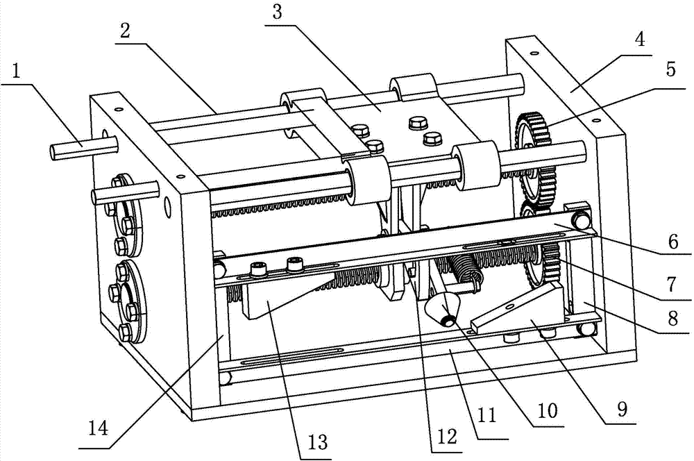
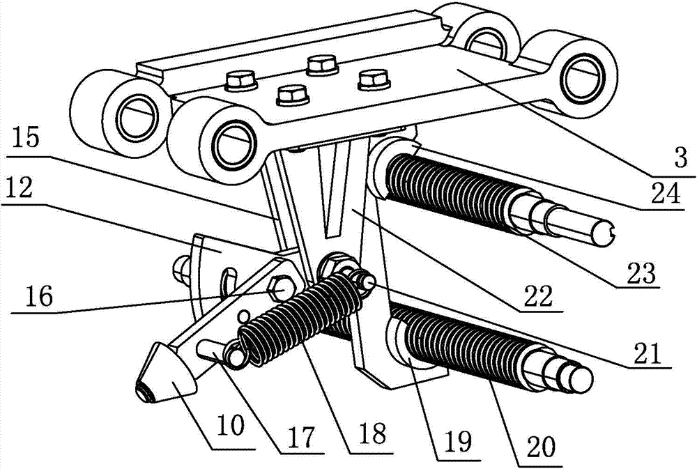
[0020] Such as figure 1 and figure 2 As shown, the present invention includes a support, a reciprocating mechanism and a drive mechanism, and the support includes two support plates 4 arranged at a distance from each other and a support for supporting and fixing the two support plates 4; the reciprocating mechanism includes a first wire Rod 23, the second screw mandrel 20, the first rocker arm 12, the sliding part 3, the slide rail 2, the second rocker arm 25, the spring 18, the left guide block 13, the right guide block 9 and the guide block mounting bracket, the first Both ends of the screw mandrel 23 and the second screw mandrel 20 are respectively supported and installed on the two support plates 4 by bearings, the slide rail 2 is a cylinder and two are arranged in parallel, and the two ends of the slide rail 2 are respectively fixed on ...


PUM


Abstract

The invention discloses a straight reciprocating motion mechanism and belongs to the field of mechanical structures. The straight reciprocating motion mechanism disclosed by the invention comprises a support, a reciprocating mechanism and a driving mechanism; the reciprocating mechanism comprises a first screw, a second screw, a first rocker, a sliding component, sliding rails, a second rocker, a spring, a left guide block, a right guide block and a guide block mounting bracket; the rear side part of the first rocker is provided with a first half nut and a second half nut; when the first rocker rotates by taking a supporting axle at the middle part of the first rocker as the center, the first screw can be matched with the first half nut or the second screw can be matched with the second half nut; the rear end of the second rocker is movably arranged at the front side part of the first rocker; the second rocker is provided with a protrusion and a spring connecting part; the protrusion is movably embedded into an arc-shaped groove in the first rocker; two ends of the spring are respectively connected with the spring connecting part and the supporting axle; the left guide block and the right guide block are respectively arranged at two ends of the sliding stroke of the sliding component; the first screw and the second screw are driven to reversely rotate by the driving mechanism, and therefore the problem of lower stability of the existing linear reciprocating motion mechanism is solved.

Description

technical field [0001] The invention belongs to the field of mechanical structures, and in particular relates to a linear reciprocating motion mechanism. Background technique [0002] In mechanical equipment, linear reciprocating motion mechanisms are often used. Common linear reciprocating motion mechanisms include: crank slider mechanism, eccentric wheel mechanism, sheave mechanism, and cam mechanism. Currently, these linear reciprocating motion mechanisms are usually One end drives the other end to move, and the reciprocating motion generated is single, and only one end can perform linear reciprocating motion. In many cases, it is not flexible enough to use, especially the linear distance during reciprocating motion is difficult to accurately adjust and control, with poor stability and low precision. Contents of the invention [0003] The purpose of the present invention is to overcome the shortcomings of the existing linear reciprocating motion mechanism, which are n...

Claims


Application Information

Patent Timeline
IPC IPC(8): F16H37/02
CPCF16H37/00F16H2702/00
Inventor 胡春祥
Owner ZHEJIANG RIFA TEXTILE MACHINERY TECH CO LTD
Learn More