Heavy-load high-speed main shaft cooling device

A technology of cooling device and high-speed spindle, which is applied in the direction of bearing cooling, transmission parts, gear lubrication/cooling, etc. It can solve the problems of poor cooling and lubrication of heavy-duty spindles, increase, and influence on speed, and achieve good cooling and lubrication effects and increase speed , increase the effect of the cooling effect

Inactive Publication Date: 2015-02-04
柳州金盛重型数控机床有限责任公司
View PDF6 Cites 2 Cited by
  • Summary
  • Abstract
  • Description
  • Claims
  • Application Information

AI Technical Summary

Problems solved by technology

[0003] The problem to be solved by the present invention is to provide a heavy-duty high-speed spindle cooling device to solve the problem of poor cooling and lubrication of the existing heavy-duty spindle, which in turn affects the increase in speed

Method used


Image

  • Heavy-load high-speed main shaft cooling device
  • Heavy-load high-speed main shaft cooling device
  • Heavy-load high-speed main shaft cooling device

Examples


Embodiment Construction

[0013] Embodiments of the present invention are described in further detail below in conjunction with the accompanying drawings:

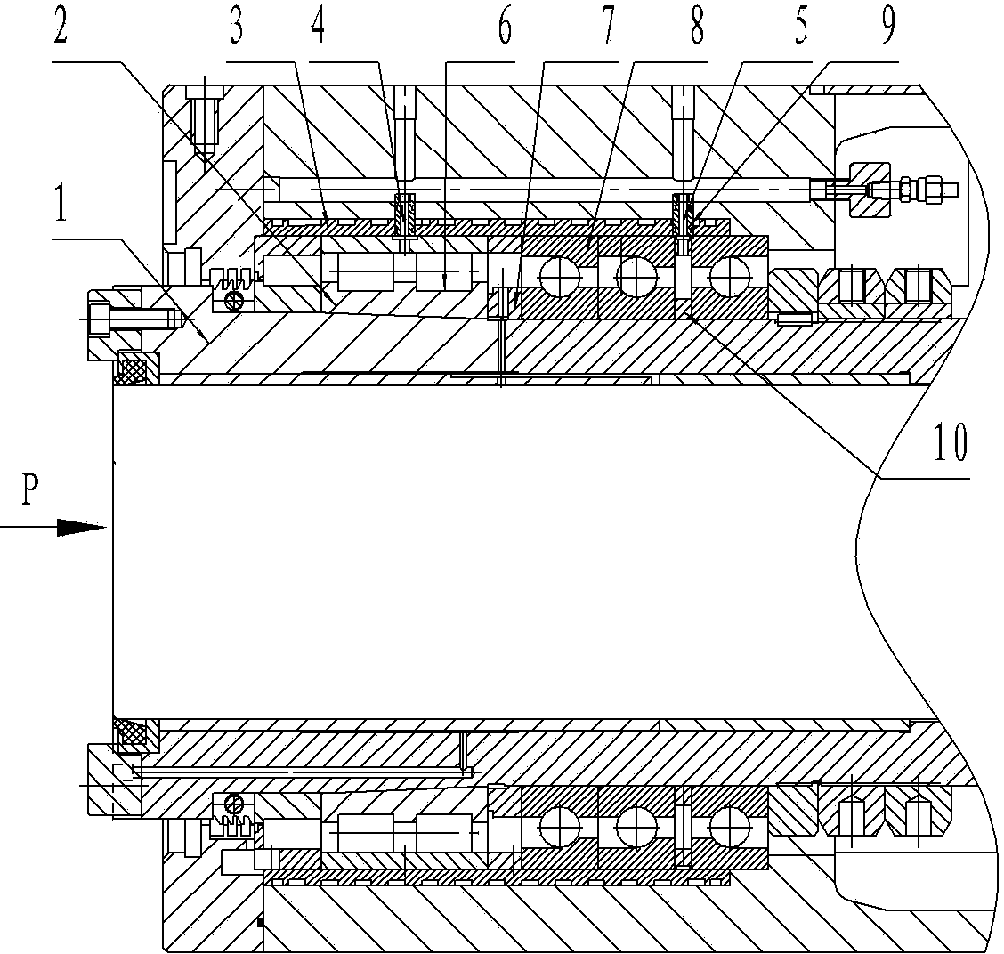
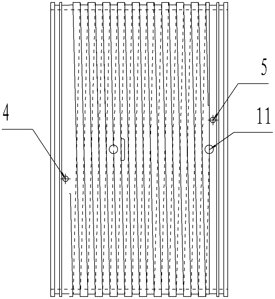
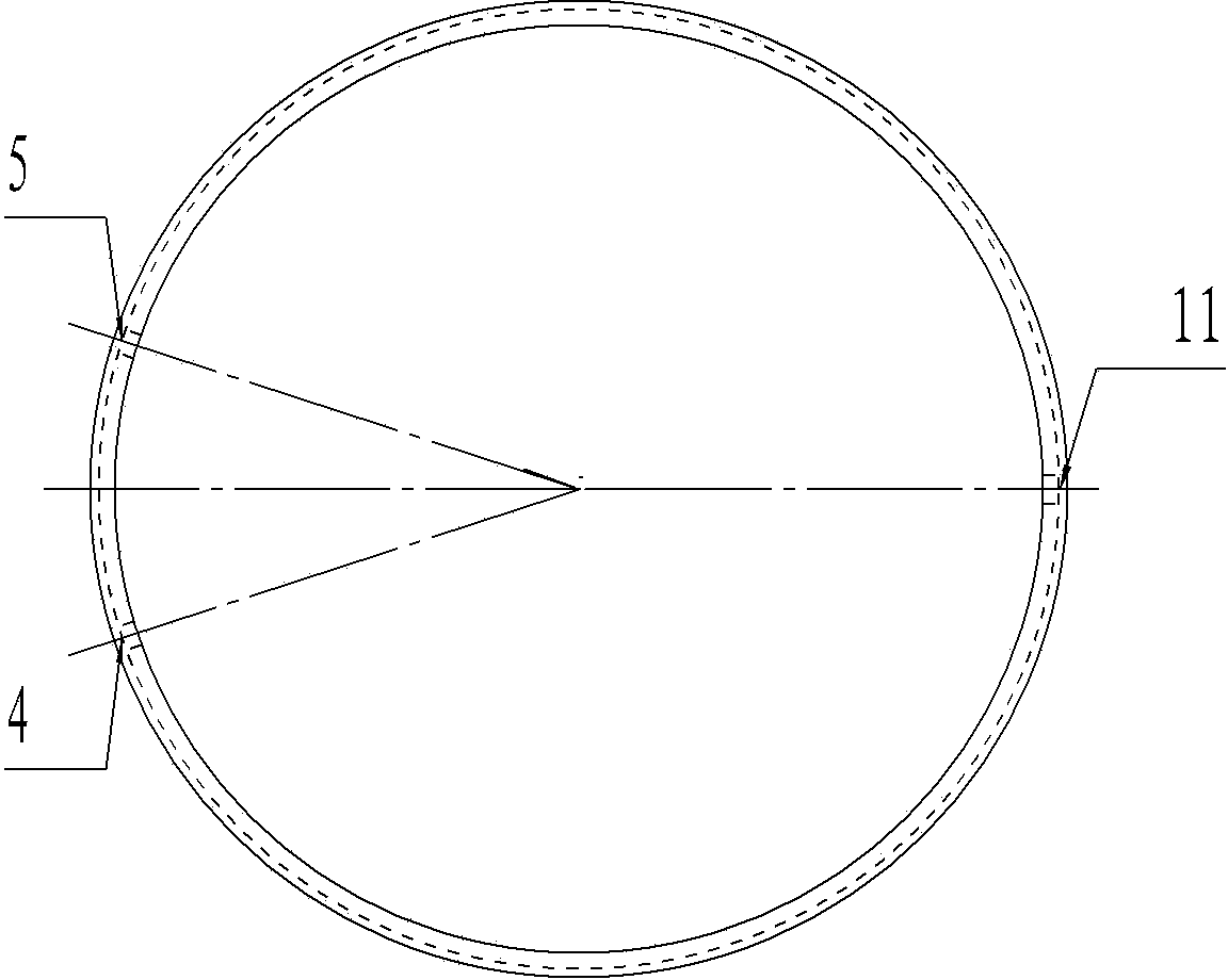
[0014] Such as figure 1 , figure 2 , image 3 The shown heavy-duty high-speed spindle cooling device includes a spindle 1, a section of the active end of the outer surface of the spindle 1 is provided with a raised platform stage 3, and the platform stage 2 is provided with a groove 6 as an oil passage. There is a cooling jacket 3 on the outer cover, and the cooling jacket 3 is connected with a section of the driven end of the main shaft 1 through a bearing 8. A spacer 7 is provided between the bearing 8 and the stage 2, and the outer surface of the cooling jacket 3 is provided with an oil inlet 5 and an oil return port. Port 4, oil inlet port 5 and oil return port 4 are provided with sealing rings 9. The oil return port is connected to the groove 6 of the stage 2 of the headstock, and there are at least two bearings 8. There are three bearings...


PUM


Abstract

The invention discloses a heavy-load high-speed main shaft cooling device. The heavy-load high-speed main shaft cooling device comprises a main shaft, wherein a projected step section is arranged on one section of a driving end of the outer surface of the main shaft; a groove serving as an oil way is formed in the step section; a cooling sleeve coats the main shaft, and is connected with one section of a driven end of the main shaft through bearings; a spacing sleeve is arranged between the bearings and the step section; an oil inlet and an oil return port are formed in the outer surface of the cooling sleeve; the oil return port is connected with the groove of the step section of the main shaft; at least two bearings are provided; a ring sleeve with an oil hole is arranged between the two bearings; and the oil inlet is connected with a gap between the bearings through the oil hole of the ring sleeve. Compared with the prior art, the heavy-load high-speed main shaft cooling device can solve the problem of influence on the acceleration of rotating speed due to weak cooling lubrication of a traditional heavy-load main shaft.

Description

technical field [0001] The invention relates to the technical field of engineering machinery processing, in particular to a cooling device for heavy-duty high-speed spindles of large-scale machinery. Background technique [0002] Due to the large size and weight of the existing large-scale machinery and heavy-duty spindles, and to ensure good coaxiality, natural cooling and grease lubrication are generally used, that is, the spindles are cooled by natural wind, and the outer surface of the spindles is cooled. Regularly inject lubricating oil to lubricate and cool. This kind of lubrication method is simple and easy to operate, and does not require additional equipment. Its disadvantage is that the applicable speed is low. At the same time, because no special cooling measures are used, it also brings difficulties to further increase the spindle speed. Spindle cooling and lubrication has become one of the technical bottlenecks in this industry. Contents of the invention [...

Claims


Application Information

Patent Timeline
Patent Type & Authority Applications(China)
IPC IPC(8): F16H57/04F16C37/00
CPCF16C37/007F16H57/0412F16H57/043F16H57/0471
Inventor 刘晓峰董岩梁兴华
Owner 柳州金盛重型数控机床有限责任公司
Why Eureka
Try Eureka