
Coin sorting machine

A technology for sorting machines and coins, which is applied in the direction of handling coins or valuable banknotes, instruments, etc., which can solve the problems of increasing the volume occupied by the shell and crowded space, and achieve the effect of simplifying the difficulty and steps of processing

Inactive Publication Date: 2015-02-04
俞劲峰
View PDF5 Cites 4 Cited by
  • Summary
  • Abstract
  • Description
  • Claims
  • Application Information

AI Technical Summary

Problems solved by technology

[0003] The traditional coin sorting machine includes a housing, a hopper located above the housing, a sorting assembly inside the housing, and a number of barrels arranged in sequence below the sorting assembly for placing different sizes of barrels. There are sorting openings for coins of different sizes on the casing and corresponding to the feed openings of the barrel, and a turntable for pushing coins through different sorting openings. In order to prevent coins from being blocked between the end of the hopper and the turntable, the Set up a toggle assembly to continuously toggle the coins falling from the end of the hopper. The toggle assembly includes a motor, a toggle shaft driven by the motor, and toggle blocks equidistantly arranged on the outer peripheral surface of the toggle shaft. However, as a toggle The motor of the shaft drive source and the motor as the drive source of the turntable increase the occupied volume of the housing virtually, making the space between the components more crowded

Method used


Image

  • Coin sorting machine
  • Coin sorting machine
  • Coin sorting machine

Examples


Embodiment Construction

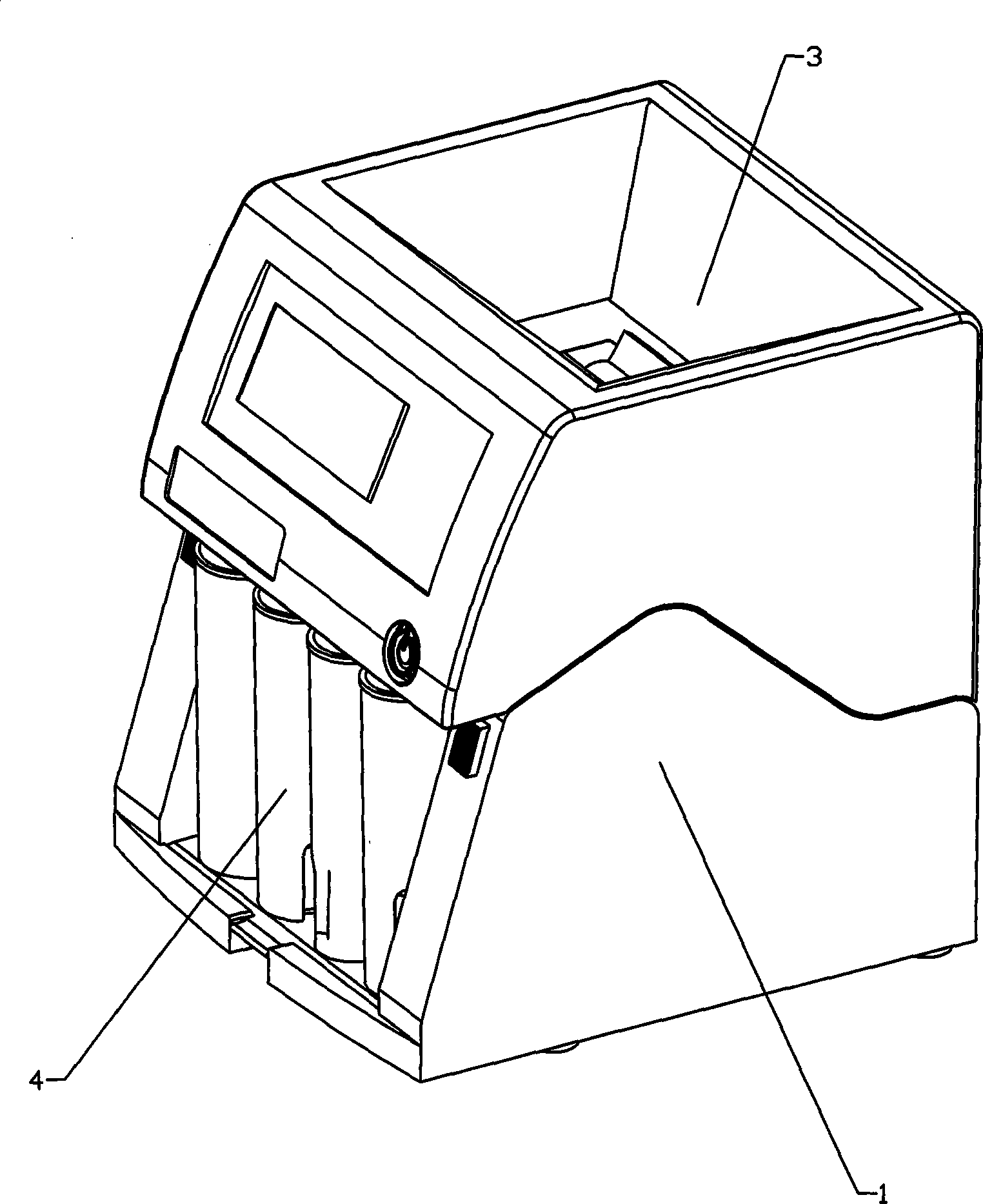
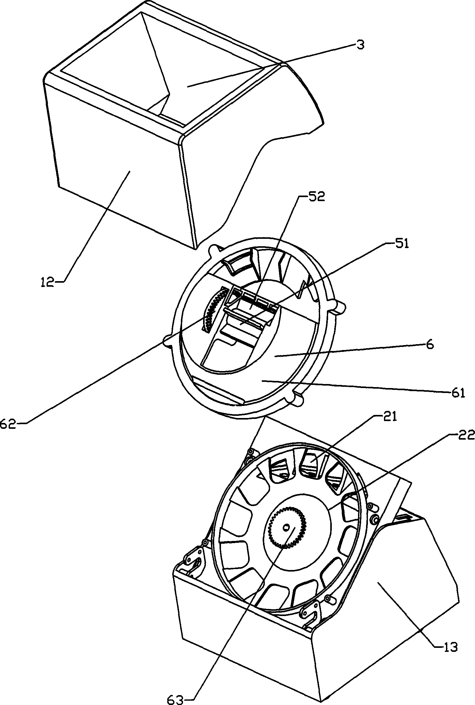
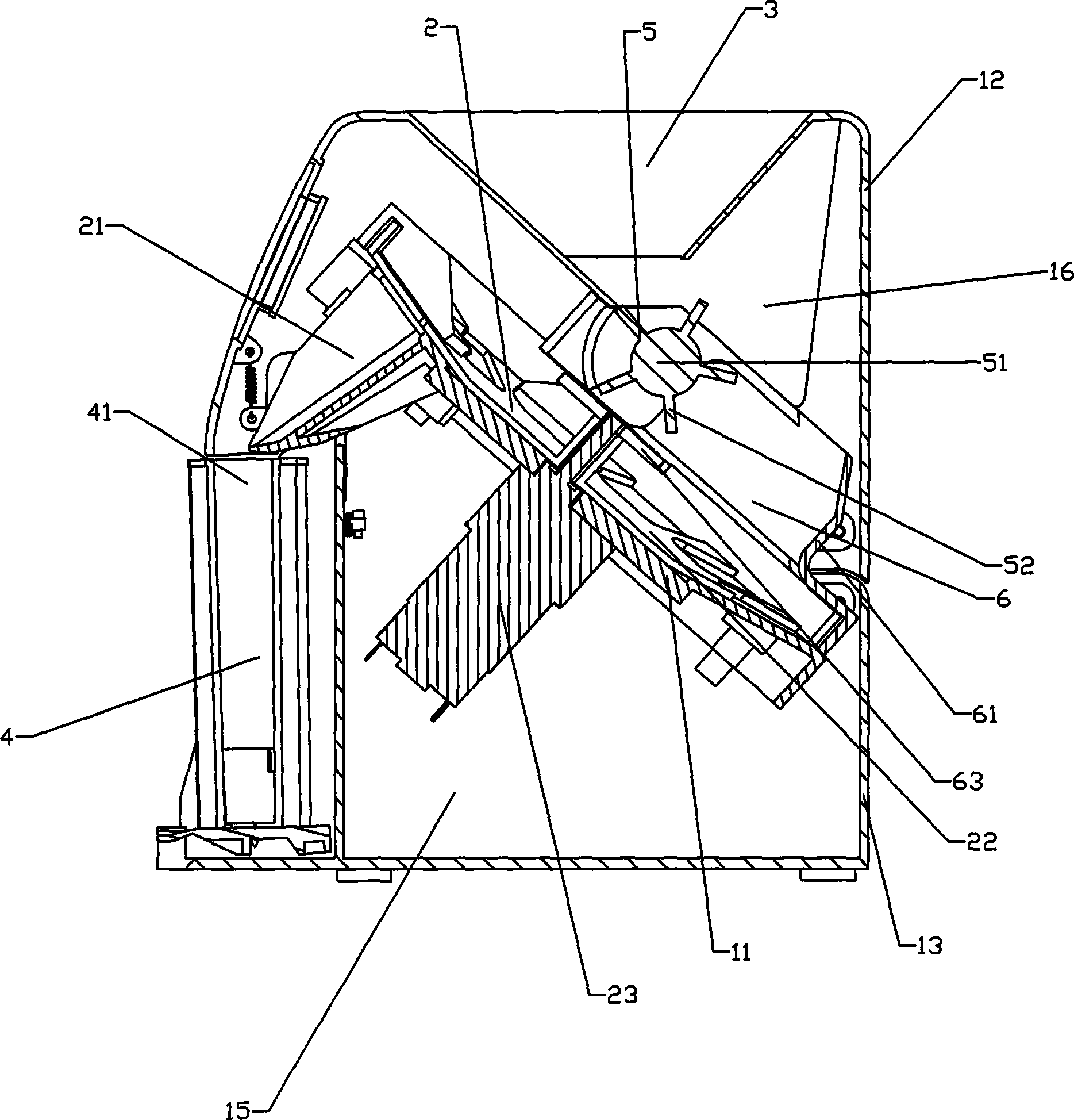
[0027] Such as figure 1 one Figure 7 As shown, the present invention discloses a coin sorting machine, including a housing 1, a sorting assembly 2 arranged in the housing 1 for sorting coins, and a hopper 3 above the sorting assembly 2 for stacking coins 1. A plurality of barrels 4 for placing coins of different sizes arranged sequentially below the sorting assembly 2. The sorting port 21 through which coins pass, the turntable 22 that pushes coins through different sorting ports 21 and falls into them, and the motor 23 that drives the turntable 22 to rotate and is fixed in the housing 1. A dial is arranged between the end of the hopper 3 and the turntable 22. The toggling assembly 5, the toggling assembly 5 includes a toggling shaft 51 and a toggling block 52 equidistantly arranged on the toggling shaft 51 along the circumferential direction, and the housing 1 is provided with a linkage that will drive the toggling shaft 51 to rotate through the turntable 22 Component 6, t...


PUM


Abstract

The invention relates to a coin sorting machine. The coin sorting machine comprises a shell, a sorting component arranged in the shell and used for sorting coins, a hopper located above the sorting component and used for storing coins, and a plurality of material barrels arranged below the sorting component in sequence and used for holding different sizes of coins, the sorting component comprises sorting holes through which different sizes of coins pass, a turn plate used for pushing coins to fall into the material barrels through different sorting holes, and a motor used for driving the turn plate to rotate and fixed in the shell, wherein the sorting holes are formed in the shell and corresponding to feed holes of the material barrels, a shifting component is arranged between the end of the hopper and the turn plate, the shifting component comprises a shifting shaft and shifting blocks which are uniformly arranged on the shifting shaft along the circumferential direction, and the shell is provided with a linkage component used for driving the shifting shaft to rotate by the aid of the turn plate. By means of said technical scheme, the coin sorting machine reduces the driving source use number.

Description

technical field [0001] The invention relates to a coin sorting device, in particular to a coin sorting machine. Background technique [0002] The coin sorting machine is a device that sorts and stacks coins mixed with coins of various sizes in stacks. It is often used in places with a large amount of coin transactions, such as shopping malls, hotels, etc., through the sorting machine The advanced sorting component automatically sorts and stacks the coins poured into the sorting machine, saving the time spent on manually sorting coins and reducing the probability of misclassification. [0003] The traditional coin sorting machine includes a housing, a hopper located above the housing, a sorting assembly inside the housing, and a number of barrels arranged in sequence below the sorting assembly for placing different sizes of barrels. There are sorting openings for coins of different sizes on the casing and corresponding to the feed openings of the barrel, and a turntable for ...

Claims


Application Information

Patent Timeline
IPC IPC(8): G07D13/00G07F9/00
CPCG07D3/02
Inventor 俞劲峰
Owner 俞劲峰
Learn More