Stepping linear motor

A linear motor and rotor shaft technology, applied in electrical components, electromechanical devices, propulsion systems, etc., can solve the problems of insufficient thread accuracy and poor concentricity, and achieve the effects of good concentricity, good versatility, and simple and reliable mold structure.

Inactive Publication Date: 2015-02-04
SHANGHAI MOONS ELECTRICAL APPLIANCE
View PDF6 Cites 10 Cited by
  • Summary
  • Abstract
  • Description
  • Claims
  • Application Information

AI Technical Summary

Problems solved by technology

The current method will obviously cause insufficient thread precision and poor concentricity due to direct injection molding of the thread.

Method used


Image

  • Stepping linear motor
  • Stepping linear motor
  • Stepping linear motor

Examples


Embodiment

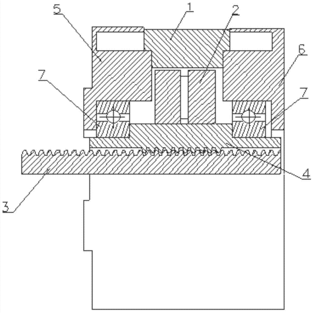
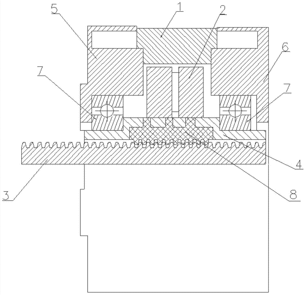
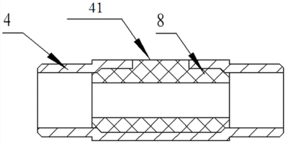
[0025] like Figure 2-4 As shown, a stepping linear motor includes a stator 1, a rotor 2, a screw 3, a rotor shaft 4, a left end cover 5, a right end cover 6, a bearing 7 and a plastic nut 8, and the screw 3 is connected to the rotor shaft 4 in transmission , the rotor shaft 4 is in transmission connection with the rotor 2, the bearings 7 are arranged at both ends of the rotor shaft 4, the left end cover 5 and the right end cover 6 are respectively arranged at both ends of the stator 1 and surround the rotor 2, and the described The plastic nut 8 is provided with threads matching the screw rod 3, and the screw rod 3 is connected with the plastic nut 8 and extends into the inside of the rotor shaft 4. The rotor shaft 4 is a hollow structure, which is used as an injection molding blank and injected into the hollow shaft.

[0026] The side of the rotor shaft 4 is provided with a through hole for fixing the plastic nut 8 . The manufacturing process of the plastic nut 8 is as fol...


PUM


Abstract

The invention relates to a stepping linear motor which comprises a stator (1), a rotor (2), a screw (3), a rotor shaft (4), a left end cover (5), a right end cover (6), bearings (7) and a plastic nut (8). The screw (3) is in transmission connection with the rotor shaft (4), the rotor shaft (4) is in transmission connection with the rotor (2), the bearings (7) are arranged at two ends of the rotor shaft (4), the left end cover (5) and the right end cover (6) are arranged at two ends of the stator (1) respectively and then enclose the rotor (2), the rotor shaft (4) is of a hollow structure, the plastic nut (8) is provided with a thread matched with the screw (3), and the screw (3) is connected with the plastic nut (8) and then extends into the rotor shaft (4). Compared with the prior art, the stepping linear motor has the advantages of high precision, fine concentricity, fine universality and the like.

Description

technical field [0001] The invention relates to a motor, in particular to a stepping linear motor. Background technique [0002] A stepping linear motor is a motor that converts rotary motion into linear motion through a screw. The stepping linear motor in the prior art makes the inside of the rotating rotor shaft into an internal thread structure, and then inserts the screw rod to realize the forward and backward movement of the screw rod when the motor rotates, as shown in the attached figure 1 As shown, wherein 1 is a stator, 2 is a rotor, 3 is a screw, 4 is a rotor shaft, 5 is a left end cover, 6 is a right end cover, and 7 is a bearing. However, threading directly inside the rotor shaft will shorten the life of the rotor. The improved method is to embed a plastic screw with self-lubricating function in the rotor shaft. How to connect the plastic and the rotor has become a problem that manufacturers need to solve. [0003] There are two connection methods for existin...

Claims


Application Information

Patent Timeline
Patent Type & Authority Applications(China)
IPC IPC(8): H02K41/03
CPCH02K7/06
Inventor 曾凯张小东
Owner SHANGHAI MOONS ELECTRICAL APPLIANCE
Why Eureka
Try Eureka