Millimeter wave flexible circular antenna array

A circular antenna and millimeter-wave technology, applied in antenna arrays, individually powered antenna arrays, antennas, etc., can solve problems such as unfavorable equipment system integration, large antenna performance changes, and unstable performance. Effect of small size and efficiency improvement

Pending Publication Date: 2021-03-09
NANJING UNIV OF POSTS & TELECOMM
View PDF0 Cites 4 Cited by
  • Summary
  • Abstract
  • Description
  • Claims
  • Application Information

AI Technical Summary

Problems solved by technology

However, there are many antenna elements in the existing rectangular antenna array, the performance of the antenna after bending changes greatly, the metal loss is high, and the performance is not stable enough under bending conditions, so the conformality is poor, which is not conducive to the integration of equipment systems

Method used


Image

  • Millimeter wave flexible circular antenna array
  • Millimeter wave flexible circular antenna array
  • Millimeter wave flexible circular antenna array

Examples


Embodiment Construction

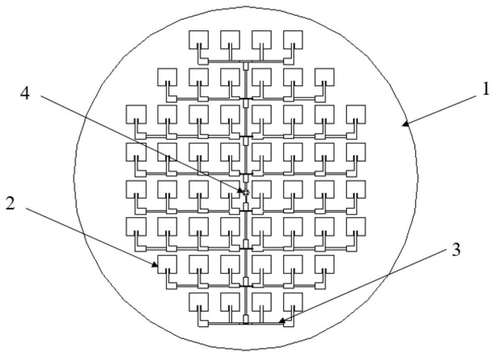
[0009] Such as figure 1 As shown, the millimeter-wave flexible circular antenna array includes a flexible dielectric substrate 1, and an antenna array 2 is arranged on the flexible dielectric substrate 1. The antenna array 2 includes 52 patch antenna units, a total of 8 rows, each row of patch antenna array units The numbers are 4, 6, 8, 8, 8, 8, 6, and 4. The patch antenna unit is a rectangular patch with a length of 3.1mm and a width of 2.9mm. The antenna array 2 is symmetrically arranged along the axis of the flexible dielectric substrate 1, and the center of the antenna array 2 is provided with a metal hole 4. The antenna array 2 adopts central feeding, and the feeding point is inserted into the patch antenna unit. The impedance transformation method is used to match the antenna unit. The patch antenna unit is fed internally through the microstrip line. The microstrip line extends into the patch antenna unit through the gap between the patch antenna units. The radius of th...


PUM

PropertyMeasurementUnit
radiusaaaaaaaaaa
thicknessaaaaaaaaaa
lengthaaaaaaaaaa

Abstract

The invention discloses a millimeter wave flexible circular antenna array, and the antenna array comprises a flexible dielectric substrate; an antenna array is arranged on the flexible dielectric substrate, the antenna array comprises a plurality of antenna units, the antenna units are connected through microstrip lines, the antenna array is symmetrically arranged along the axis of the flexible dielectric substrate, and a metal circular hole is formed in the center of the antenna array. The millimeter wave flexible circular antenna array structure is light in weight and small in size, the bendability of the antenna is improved on the premise of ensuring the performance of the antenna array, and the conformality between the antenna and equipment is good.

Description

technical field [0001] The present invention relates to a circular antenna array, and more particularly, to a millimeter-wave flexible circular antenna array. Background technique [0002] As a key component of a wireless communication system, the transmission and reception of radio waves are accomplished by antennas. In the field of antenna research, the conformality between the antenna and the installation environment has always been a research hotspot. With the development of new technologies such as wearable devices, there is an increasing need for antennas to be highly integrated with devices. On the other hand, with the advancement and upgrading of technology, the communication system is also developing towards a higher working frequency band or even a millimeter wave band, in order to obtain smaller system size, wider working bandwidth and better system performance. Flexible electronics technology is a newly emerging technology. Each device is fabricated on a thin, ...

Claims


Application Information

Patent Timeline
Patent Type & Authority Applications(China)
IPC IPC(8): H01Q21/06
CPCH01Q21/065
Inventor 陈董陆禹薇杨旭袁锴张洪林
Owner NANJING UNIV OF POSTS & TELECOMM
Why Eureka
Try Eureka