
Vehicle power transmission device

A power transmission device and vehicle technology, applied in the field of power devices, can solve problems such as power loss and lubricating oil deterioration

Inactive Publication Date: 2015-02-04
TOYOTA JIDOSHA KK
View PDF12 Cites 6 Cited by
  • Summary
  • Abstract
  • Description
  • Claims
  • Application Information

AI Technical Summary

Problems solved by technology

As a result, like the device described in the above-mentioned JP-A-2005-308041, a large rotational speed difference occurs between the sun gear, the pinion gear, and the ring gear, which may cause loss of power, deterioration of lubricating oil, noise or The possibility of the cause of the vibration

Method used


Image

  • Vehicle power transmission device
  • Vehicle power transmission device
  • Vehicle power transmission device

Examples


Embodiment Construction

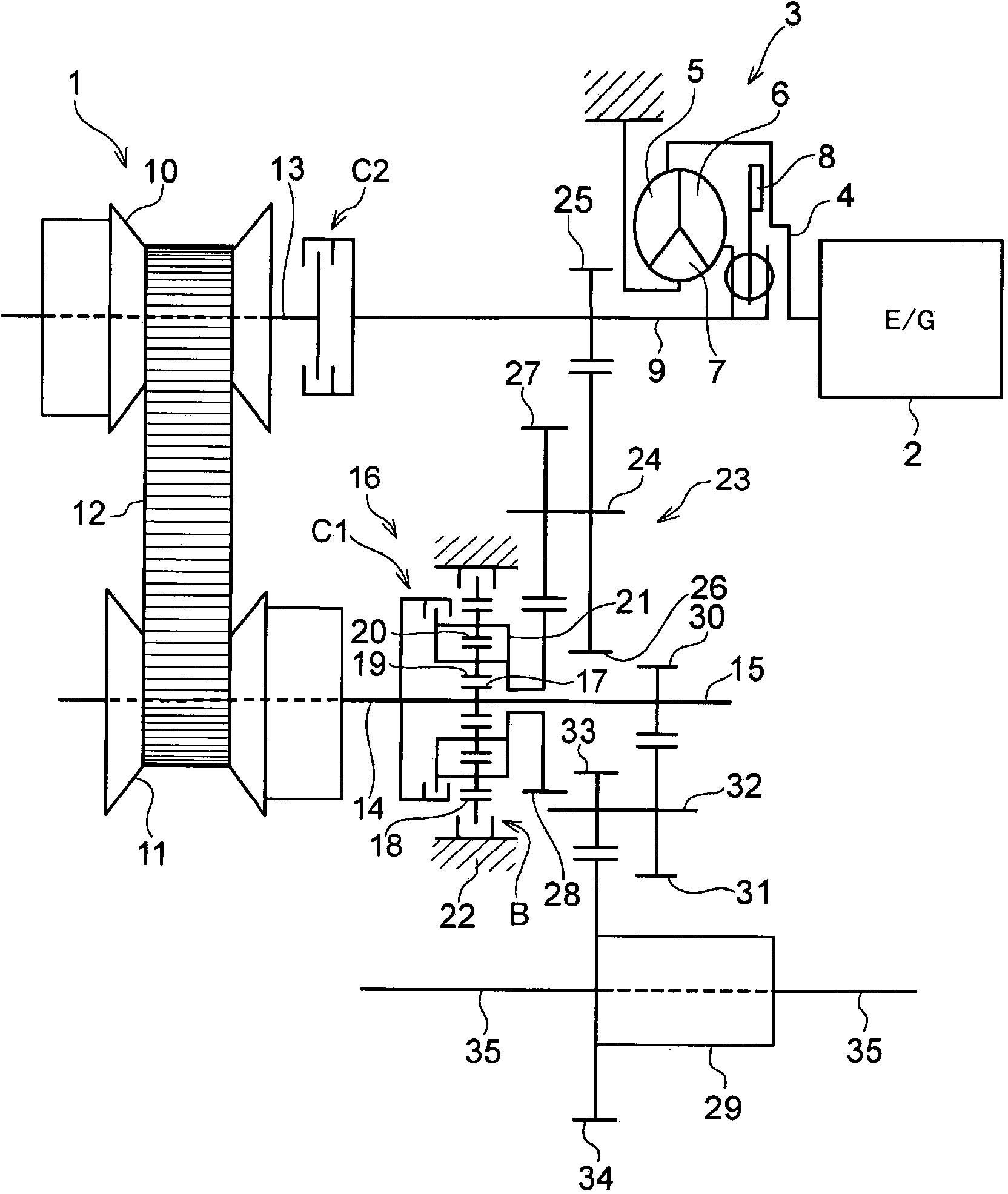
[0052] Next, the present invention will be explained with reference to specific examples. The power transmission device according to the present invention is a device for transmitting power output from a driving power source such as an engine or an electric motor to the driving wheels, and is a device having a speed change function. That is, it is a device generally called a power train or a transaxle. In particular, the device targeted by the present invention is a power transmission device having a continuously variable transmission arranged in parallel between an input shaft and an output shaft and a gear train with a predetermined speed ratio (gear ratio). The continuously variable transmission may also be a belt type continuously variable transmission or a toroidal continuously variable transmission known in the past. The belt-type continuously variable transmission is suitable for power transmission devices mounted on FF vehicles (front-engine, front-wheel drive vehicles...


PUM


Abstract

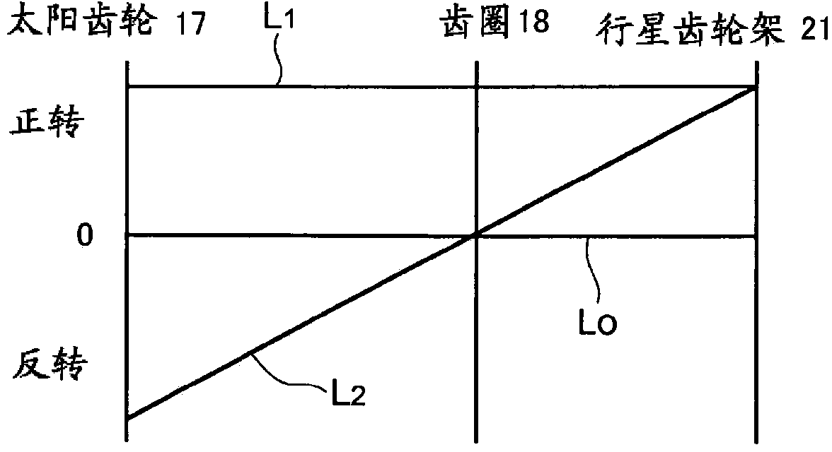
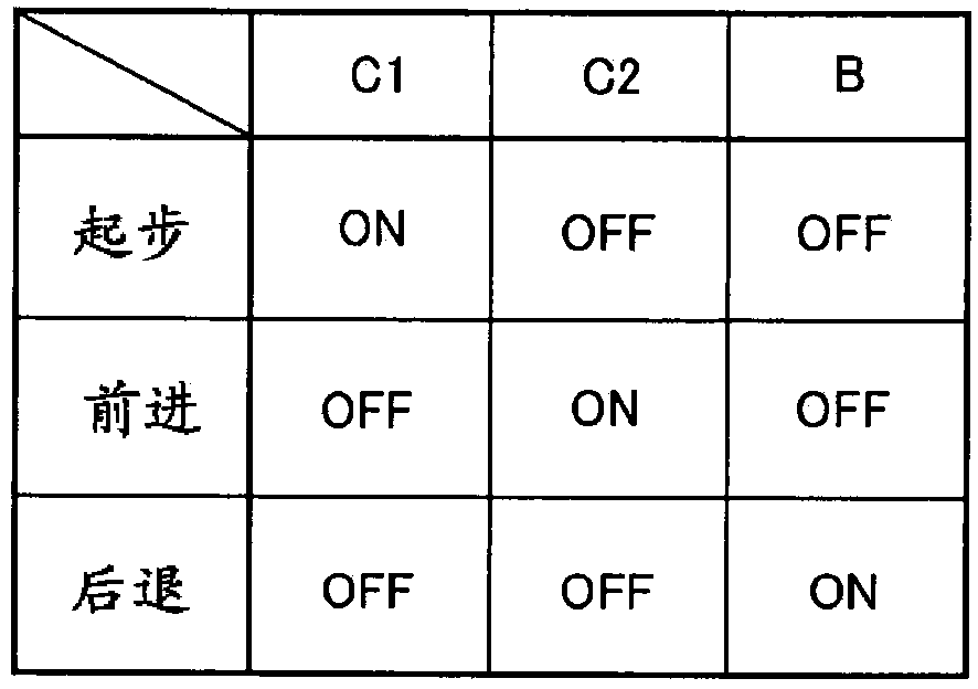
A vehicle power transmission device in which a continuously variable transmission for continuously changing the transmission gear ratio, and a gear train are disposed between an input shaft to which the torque outputted from a drive power source is inputted and the output shaft which outputs the torque such that the torque can be transmitted between the input shaft and the output shaft, the gear train having a middle shaft disposed on a position that is different from the input shaft and the output shaft and setting at least one transmission gear ratio that cannot be set by the continuously variable transmission, wherein: a forward / reverse switching mechanism for carrying out a differential action by means of three rotating elements is disposed along the same axial line as the output shaft or the middle shaft, the three rotating element being an input element, an output element, and a reaction element for rotating the input element and the output element in the opposite direction from one another as a consequence of the rotation of the reaction element being stopped; a first clutch mechanism for connecting at least two of the three rotating elements and a brake mechanism for stopping the rotation of the reaction element are provided; the input shaft and the output shaft are in communication with one another via the continuously variable transmission; a second clutch mechanism for transmitting and blocking the torque is disposed on a torque transmission path extending from the input shaft to the continuously variable transmission and finally to the output shaft; and the input shaft and the output shaft are in communication with one another via the gear train and the forward / reverse switching mechanism.

Description

Technical field [0001] The present invention relates to a device for transmitting power output from a drive source of a vehicle, and more particularly, to a power transmission device equipped with a transmission path including a continuously variable transmission and other transmission paths arranged in parallel with the transmission path. Background technique [0002] An internal combustion engine generally used as a driving force source for a vehicle has a characteristic that the output torque increases in response to an increase in the rotation speed. In contrast, the driving force required by the vehicle is generally large at low vehicle speeds and relatively small at high vehicle speeds. That is, in a vehicle, a torque opposite to the torque based on the output characteristic of the internal combustion engine is required. In addition, the efficient operating point of the internal combustion engine is limited. Therefore, a vehicle using an internal combustion engine as a dr...

Claims


Application Information

Patent Timeline
Patent Type & Authority Applications(China)
IPC IPC(8): F16H37/02
CPCF16H2200/0008F16H37/022F16H2037/026F16H37/021F16H2200/2005F16H2200/2035
Inventor 吉田伦生中田博文小林大介吉野弘绍
Owner TOYOTA JIDOSHA KK
Learn More