Double-conic disc friction stepless speed changer

A continuously variable transmission, cone-disc technology, applied in friction transmission devices, elements with teeth, belts/chains/gears, etc., can solve the problems of low transmission efficiency, high manufacturing cost, and high control requirements, and achieve a large adjustment range. , The effect of low manufacturing cost and large gear ratio

Inactive Publication Date: 2007-03-21
江从寿
View PDF1 Cites 3 Cited by
  • Summary
  • Abstract
  • Description
  • Claims
  • Application Information

AI Technical Summary

Problems solved by technology

The manual transmission device uses multiple pairs of gears to change the combination of the gears through manual manipulation to change the transmission ratio, so as to achieve the purpose of speed change. The advantages of the manual transmission device are simple structure, low cost, and high transmission efficiency. The disadvantages are Unable to realize continuous smooth stepless transmission, high control requirements and inconvenient driving
There are currently three types of automatic transmission devices: the first one uses a hydraulic torque converter and a multi-stage mechanical transmission device, which has the advantages of smooth starting and simplified operation, but the disadvantage of complex structure and high manufacturing and maintenance costs; The hydraulic or electric servo device replaces the manual operation. The disadvantage is that it cannot realize stepless speed change and the transmission efficiency is low. Change the transmission ratio to achieve continuous and smooth speed change. The disadvantage is that the quality requirements of the transmission belt are relatively high, and the manufacturing and maintenance costs are high.
For example, the utility model patent 02221636.7 has the advantage of being able to realize continuous and smooth continuously variable transmission, but the disadvantage is that the structure is more complicated, the manufacturing cost is higher, and the range of transmission ratio variation is not large enough

Method used


Image

  • Double-conic disc friction stepless speed changer

Examples


specific Embodiment approach

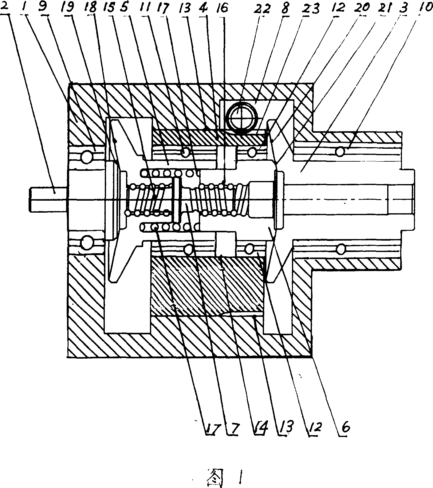
[0009] The specific implementation is as follows: the input shaft 2 is mounted on the left end of the casing 1 with the bearing 9, and the output shaft 3 is mounted on the right end of the casing 1 with the bearing 10; the eccentric sleeve 4 is a cylinder with an inner hole, which is installed in the inner hole 13 of the casing, and The distance and position between the shaft center of the sleeve inner hole 14 and the shaft center of the housing inner hole 13 can be changed. The intermediary friction transmission disc 5 is installed in the eccentric sleeve inner hole 14 with the bearing 11, and the intermediary transmission shaft 6 is installed in the eccentric sleeve inner hole 14 with the bearing 12. In the inner hole 14 of the eccentric sleeve, the intermediate friction transmission disc 5 and the intermediate transmission shaft 6 can rotate in the inner hole 14 of the eccentric sleeve and move along the axial direction; It is a reverse thread 16, the center of the intermedi...


PUM


Abstract

The present invention relates to a double conical disk friction stepless speed changer. It is characterized by that its input shaft is mounted in the left end of external shell and its output shaft is mounted in the right end of said external shell; the eccentric sleeve is mounted in the inner hole of external shell, the medium friction drive disk and medium drive shaft are mounted in the inner hole of eccentric sleeve; the double-head bidirectional screw rod left end is mounted into the positive screw hole of medium friction drive disk by means of positive screw threads, and the double-head bidirectional screw rod right end is mounted into the negative screw hole of medium drive shaft by means of negative screw threads; the left end face of medium friction drive disk is conical recessed surface, the right end of input shaft is conical projected surface; the left end face of output shaft is conical recessed surface, the right end of medium drive shaft is conical projected surface; and the eccentric sleeve is driven by eccentric sleeve drive device and is rotated.

Description

technical field [0001] The invention belongs to the technical field of a transmission device that transmits rotational motion with a variable speed ratio by using friction between rotating elements. Background technique [0002] The continuous smooth continuously variable transmission is an ideal transmission device, but generally speaking, the structure is more complicated and the cost is higher. Taking the automobile transmission device as an example, the automobile transmission device is divided into two categories: manual transmission device and automatic transmission device. The manual transmission device uses multiple pairs of gears to change the combination of the gears through manual manipulation to change the transmission ratio, so as to achieve the purpose of speed change. The advantages of the manual transmission device are simple structure, low cost, and high transmission efficiency. The disadvantages are Continuous smooth continuously variable speed cannot be r...

Claims


Application Information

Patent Timeline
Patent Type & Authority Applications(China)
IPC IPC(8): F16H15/06F16H61/04
Inventor 江从寿
Owner 江从寿
Why Eureka
Try Eureka