
Stepwise gun wiping robot and method of use thereof

A robotic, step-by-step technology used in weapon attachments, offensive equipment, weapon cleaning devices, etc. to increase the effective working range and improve portability

Inactive Publication Date: 2008-04-09
TAIYUAN UNIV OF TECH
View PDF3 Cites 13 Cited by
  • Summary
  • Abstract
  • Description
  • Claims
  • Application Information

AI Technical Summary

Problems solved by technology

[0003] The purpose of a step-by-step gun cleaning robot of the present invention is to solve the unsolvable and difficult problems in the above-mentioned prior art, thereby providing a robot that can remove and maintain the residual copper stains and nylon stains on the inner surface of the gun, and can improve A technical solution for a step-by-step gun wiping robot that prolongs weapon life and striking accuracy

Method used

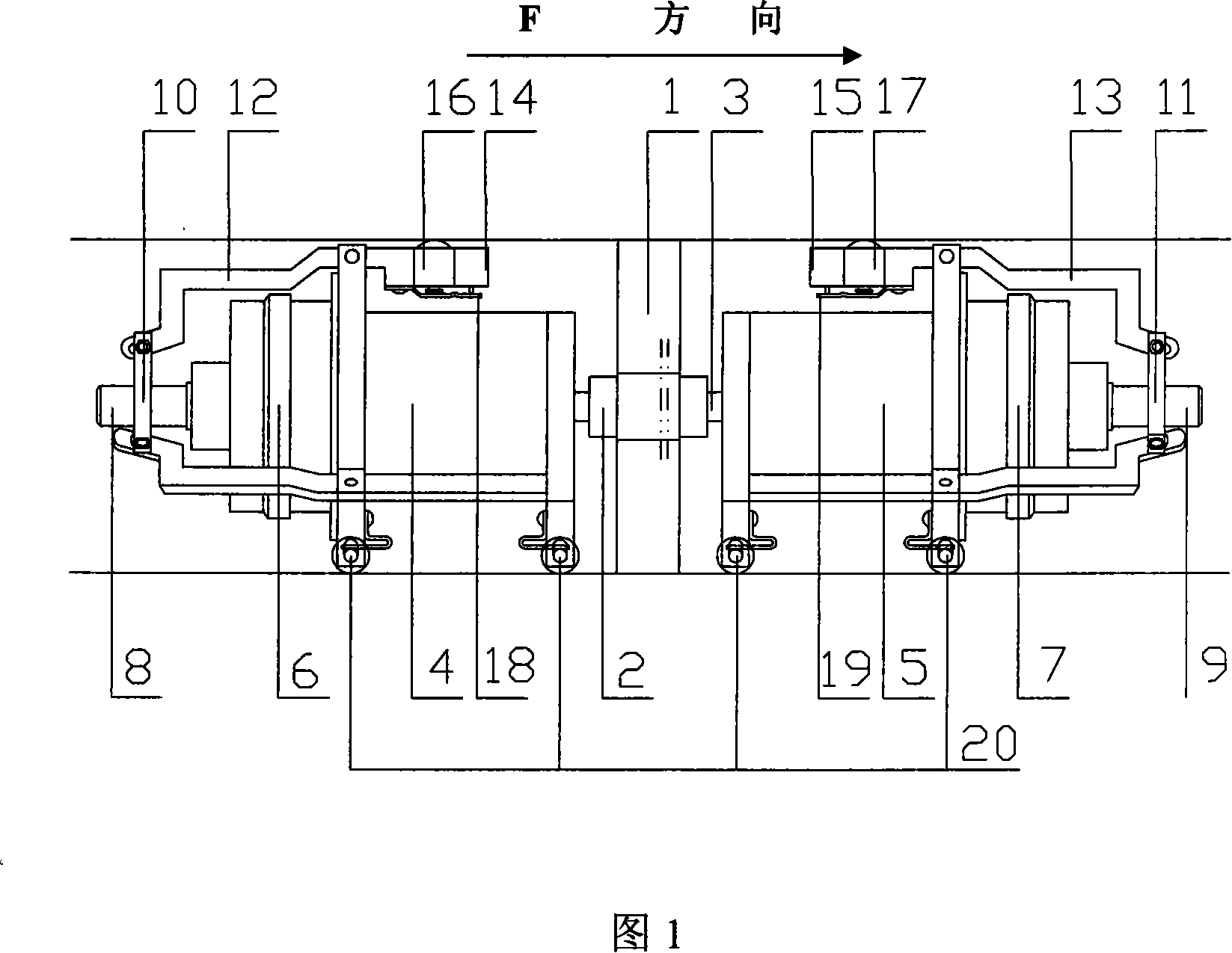

Image

  • Stepwise gun wiping robot and method of use thereof

Examples


Embodiment approach 1

[0033]For a certain type of artillery, a step-by-step cleaning robot consists of a cleaning head 1, an internal thread sleeve 2, a moving screw 3, a first biaxial stepping motor 4, a second biaxial stepping motor 5, and a first electromagnetic clutch. 6. The second electromagnetic clutch 7, the first compression screw 8, the second compression screw 9, the first compression nut 10, the second compression nut 11, the first lifting compression arm 12, the second lifting compression Arm 13, the first normally closed type micro switch 14, the second normally closed type micro switch 15, the first rubber spring 16, the second rubber spring 17, the first micro reed 18, the second micro reed 19 and walking The wheel train and the support frame 20 are composed of the cleaning head 1 installed on the outside of the internally threaded sleeve 2 and fixedly connected with the internally threaded sleeve 2 by screws, and the moving screw 3 is connected with the internally threaded sleeve 2 ...

Embodiment approach 2

[0036] The dual-axis stepping motor adopts a holding torque of 0.65N m; the electromagnetic clutch adopts a clutch with a voltage of DC 24V, a dynamic torque of 4N m, a static torque of 5N m, and an electric high rotation speed of 4000rpm. 1 Installed on the outside of the internally threaded sleeve 2 and fixedly connected with the internally threaded sleeve 2 by welding, the fixed number of pulses sent by the programmable logic controller PLC is 60,000, and the corresponding first biaxial stepper motor 4 and the second The number of rotations of the shafts of the two biaxial stepper motors 5 is 300, and the others are the same as in Embodiment 1.

Embodiment approach 3

[0038] The dual-axis stepping motor adopts a holding torque of 1.72N m; the electromagnetic clutch adopts a clutch with a voltage of DC 24V, a dynamic torque of 32N m, a static torque of 40N m, and a high rotation speed of 2000rpm. 1 is installed on the outside of the internally threaded sleeve 2 and fixedly connected with the internally threaded sleeve 2 as a whole by riveting. The fixed number of pulses sent by the programmable logic controller PLC is 80,000, and the corresponding number of rotations of the shafts of the first biaxial stepper motor 4 and the second biaxial stepper motor 5 is 400. Others are the same as in Embodiment 1.


PUM


Abstract

The invention relates to a stepwise gun-wiping robot and a use method, belongs to mechanical engineering and military science technical field, and is characterized in that the invention is a robot, of which driving force is provided by a stepper motor, a screw and an internal threaded sleeve move forward or backward in pace, an impacted arm and a road wheel train support realize walking in a gun tube, and the advance of the robot and the control of the gun-wiping action without skidding are realized by a programmable logic controller (PLC). The invention provides a technical proposal of a stepwise gun-wiping robot by which residual copper stains and nylon stains left on the inner face of a canal of various artilleries after being fired can be cleared and maintained, and the weapon life and the fire accuracy can be prolonged and improved.

Description

1. Technical field [0001] The invention relates to a step-by-step gun cleaning robot and its use method, which belong to the field of mechanical engineering and military science and technology. device. 2. Background technology [0002] At present, the wiping of the inner surface of the gun barrel of the combat troops is still done by pushing and pulling the cleaning rods by several soldiers, which not only consumes manpower and time, but also has a low degree of wiping and cleaning. It cannot meet and adapt to the operational requirements of modern high-tech warfare. So the current combat troops urgently need a set of highly automated and portable artillery wiping, cleaning and maintenance devices. However, the existing documents and patents are not applicable to the wiping of the gun bore, as described in the patent No. ZL200410068852.0 single-motor single-drive straight-forward wheeled small-scale pipeline robot moving mechanism and the patent No. ZL 97239911.9 brush-typ...

Claims


Application Information

Patent Timeline
IPC IPC(8): F41A29/00
Inventor 李元宗郝鹏飞郭红生
Owner TAIYUAN UNIV OF TECH
Learn More