Cooling container

A container and cooling part technology, applied in coolers, refrigerated rooms, refrigerators, etc., to achieve high-efficiency cooling

Active Publication Date: 2015-02-04
FURUKAWA ELECTRIC CO LTD
View PDF6 Cites 4 Cited by
  • Summary
  • Abstract
  • Description
  • Claims
  • Application Information

AI Technical Summary

Problems solved by technology

[0005] In this cryostat, the refrigerant in the refrigerant container must be kept at an extremely low temperature. However, the internal superconducting coil must be connected to the external power supply through a current wire, and heat intrusion from the current wire connecting the inside and outside cannot be avoided.

Method used


Image

  • Cooling container
  • Cooling container
  • Cooling container

Examples


no. 1 Embodiment approach

[0044] Hereinafter, the first embodiment of the present invention will be described in detail with reference to the drawings.

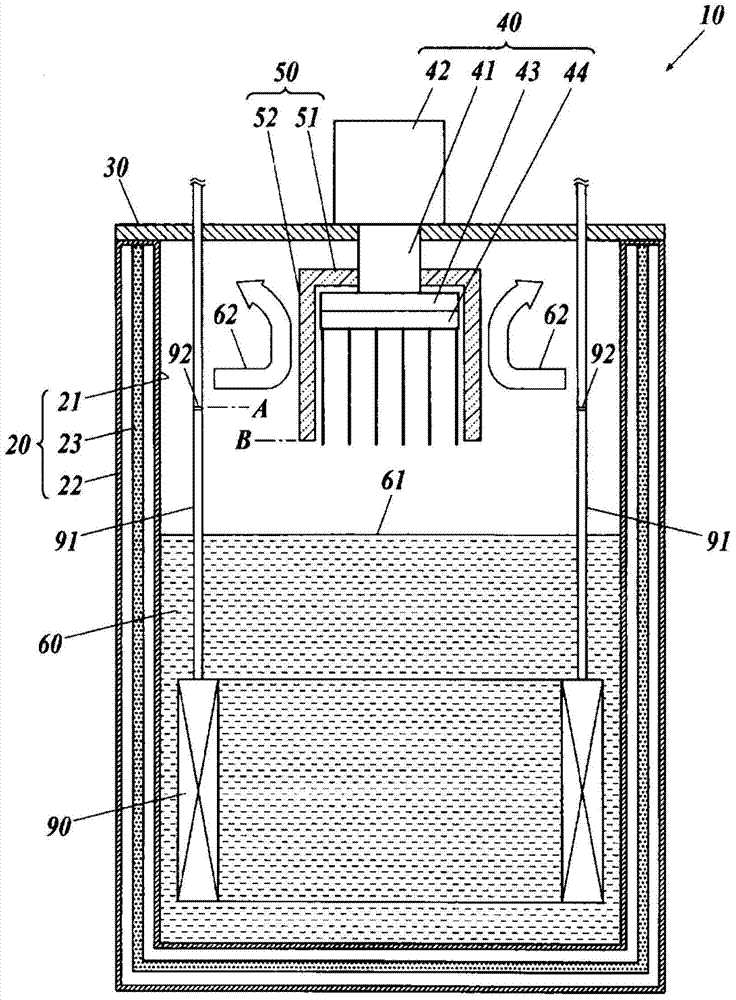
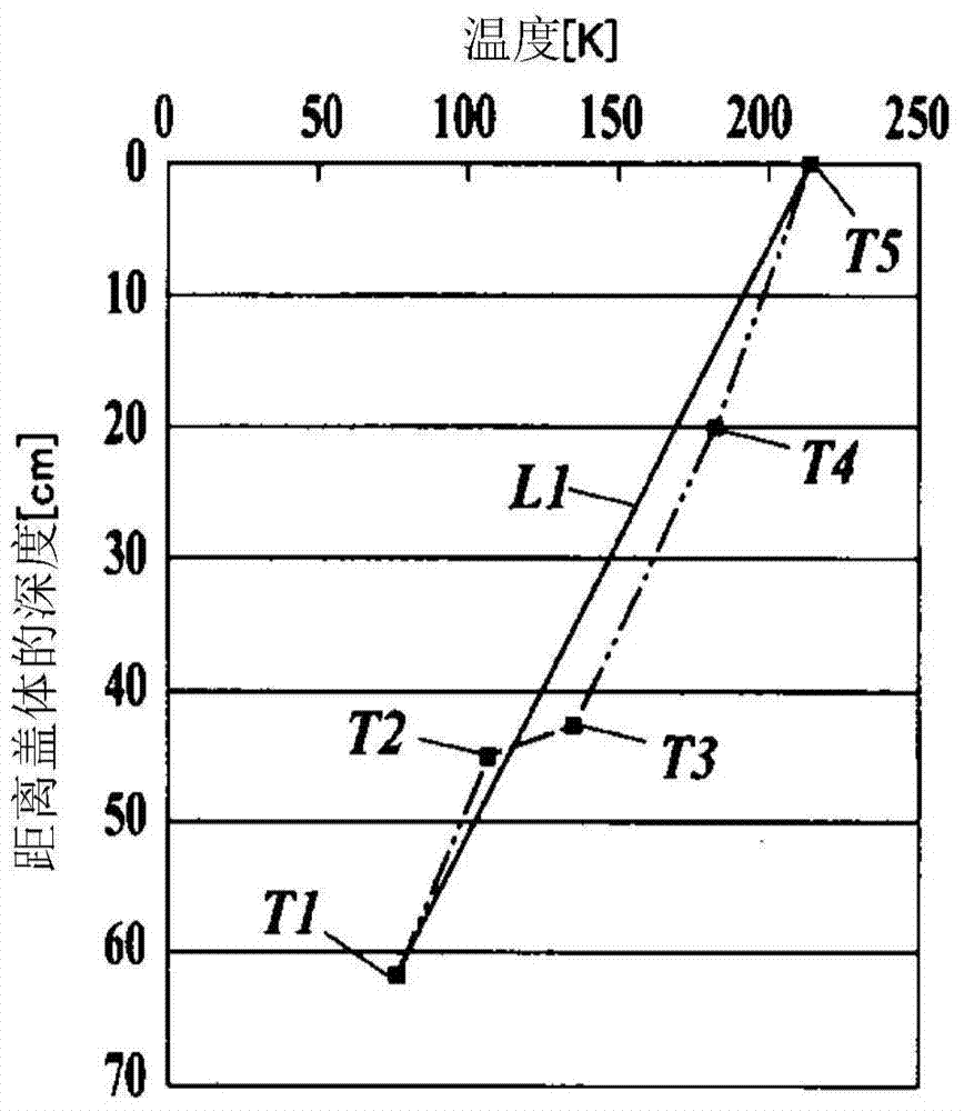
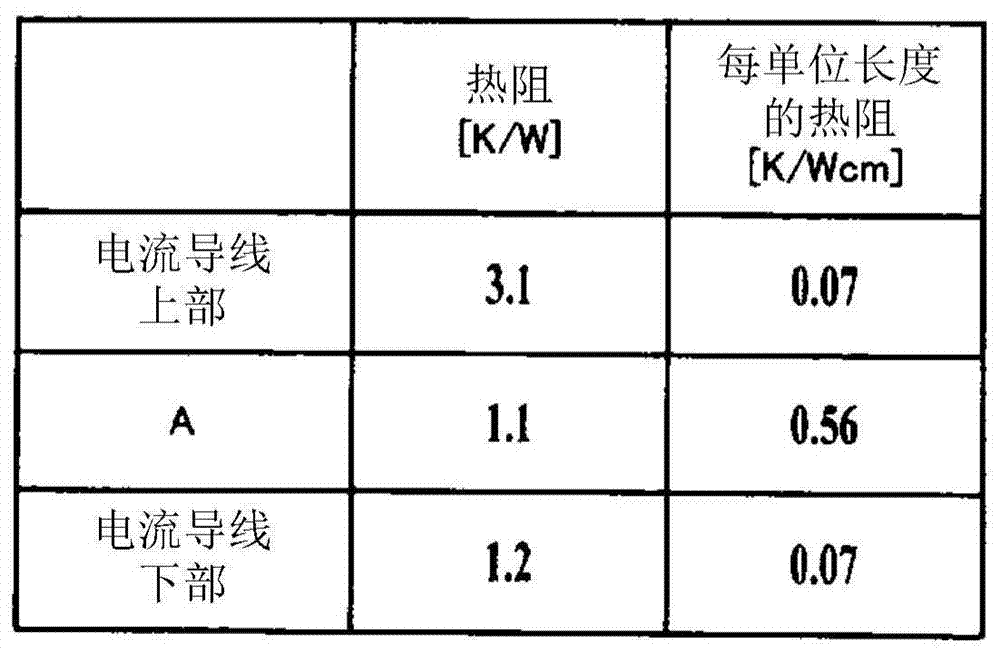
[0045] In this first embodiment, a cryostat 10 as a cooling container for accommodating and cooling a superconducting coil 90 as a superconducting device serving as an object to be cooled will be described. figure 1 is a sectional view of the cryostat 10 along a vertical plane.

[0046] This cryostat 10 has: a refrigerant container 20 which has a vacuum-insulated inner container 21 and an outer container 22 for accommodating liquid nitrogen 60 as a liquid refrigerant and a superconducting coil 90; and a cover 30 capable of sealing the refrigerant. The upper opening of the container 20; the refrigerator 40 as a cooling unit, which cools the liquid nitrogen 60 in the inner container 21; refrigerant gas; and a pair of current wires 91 , 91 for each phase of the superconducting coil 90 for conducting electricity between the superconducting coil 90 and th...

no. 2 Embodiment approach

[0096] Hereinafter, a second embodiment of the present invention will be described in detail with reference to the drawings.

[0097] Figure 5 It is a cross-sectional view along a vertical plane of a cryostat 10C according to the second embodiment.

[0098] This cryostat 10C differs from the cryostat 10 in that it has a new partition wall portion 93 surrounding each current lead 91 . Hereinafter, only the differences between the cryostat 10C and the cryostat 10 will be described, and the same reference numerals will be assigned to the same structures, and repeated description will be omitted.

[0099] As described above, each current lead 91 has the partition wall portion 93 surrounding the current lead 91 .

[0100] The partition wall portion 93 is a cylindrical body made of a heat insulating material into which the current lead 91 is inserted with some play, and its upper end is attached to the lower surface of the cover body 30 by bonding or the like, and supported in a ...


PUM


Abstract

A cooling container includes a coolant container (20) for accommodating an object to be cooled (90) and a liquid coolant (60) in the inside, a lid member (30) capable of closing the upper opening of the coolant container, a cooling means (40) hung from and supported by the lid member and having a cooling section at the lower end, and electric current leads (91) hung from and supported by the lid member, for making electric current flow into the object to be cooled inside the coolant container. The electric current leads each have a thermal resistance section (92) having a higher thermal resistance than the surrounding portions, at a position above the liquid surface of the liquid coolant in the coolant container. Between the thermal resistance sections and the cooling section of the cooling means, a partition section (50) made from a heat insulation material is provided such that the lower end of the partition section is below the thermal resistance sections. As a result, the effect of penetrating heat can be prevented to allow the inside of the coolant container to be efficiently cooled.

Description

technical field [0001] The present invention relates to a cooling container for cooling an object to be cooled by means of a liquid refrigerant in the container. Background technique [0002] Superconducting magnetic field generators used in SMES (Superconducting Magnetic Energy Storage), superconducting transformers, superconducting current limiters, NMR (Nuclear Magnetic Resonance: Nuclear Magnetic Resonance), semiconductor pull-in devices, etc. In the field of conductive magnets and the like, superconducting wires or superconducting thin films using superconductors represented by yttrium-based and bismuth-based superconductors are used. To superconduct these superconducting wires, they must be cooled to extremely low temperatures. [0003] Usually, a superconducting wire is stored in a state of a superconducting coil in a vacuum-insulated cooling container called a cryostat for cooling. [0004] A conventional cryostat includes: a cryogen container for accommodating a s...

Claims


Application Information

Patent Timeline
Patent Type & Authority Applications(China)
IPC IPC(8): H01L39/04F25B9/14F25D13/00
CPCF25D19/006F25B2400/17H01F6/04H01B12/02H01B12/06H01B12/16
Inventor 笠原甫松冈太郎松井正和
Owner FURUKAWA ELECTRIC CO LTD
Why Eureka
Try Eureka