Continuous hinge circle-rolling device

A rolling device and hinge technology, which is applied in the field of mold groups, can solve problems such as low efficiency and waste of labor, and achieve the effects of high precision, precise continuous rolling, and high production efficiency

Inactive Publication Date: 2015-02-11
重庆市大足区君帅五金加工厂
View PDF5 Cites 13 Cited by
  • Summary
  • Abstract
  • Description
  • Claims
  • Application Information

AI Technical Summary

Problems solved by technology

[0002] A hinge is a mechanical device used to connect two solids and allow them to rotate. It includes two identical blades and a connecting shaft that hinges the two blades. It passes feeding, punching round holes, cutting off burrs, The processes of cutting square holes, round corner forming, 90° bending, round forming and cutting are completed. In the prior art, the processing of hinge blades is processed sequentially by multiple single-station molds, and the multiple molds are independent of each other. In particular, this asymmetric combination leaf blade can only start the processing of the next link after one processing link is completed. If a link needs a worker, then multiple workers need to cooperate with each other to complete the entire hinge leaf. processing, which is not only inefficient, but also a waste of labor

Method used


Image

  • Continuous hinge circle-rolling device

Examples


Embodiment Construction

[0016] The preferred embodiments of the present invention will be described in detail below with reference to the accompanying drawings.

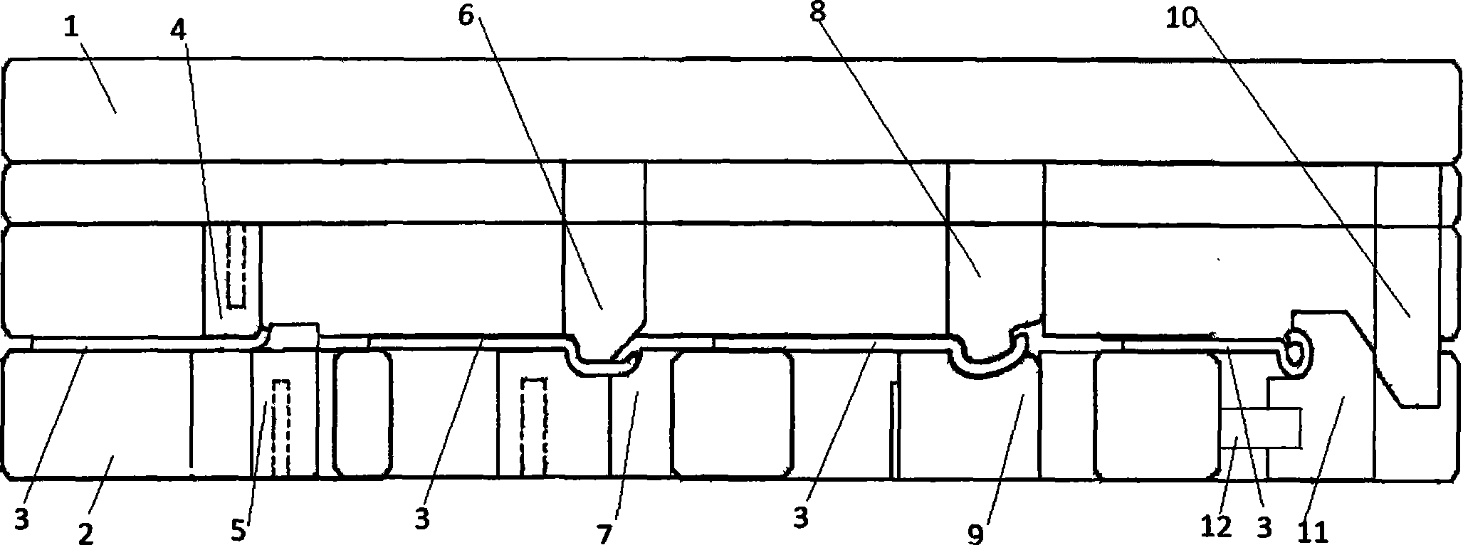
[0017] As shown in Figure 1, it is a structural schematic diagram of the hinge continuous rolling device of the present invention. A hinge continuous rolling device of the present invention includes an upper mold 1 and a lower mold 2, and the upper mold 1 and the lower mold 2 are passed through the inner precision The guide posts are connected, and a production line for stamping workpieces 3 is formed between the upper die 1 and the lower die 2. The bottom of the upper die 1 is sequentially provided with end round punches 4, root round punches 6, and 45° Rolling punch 8 and rolling forming punch 10, the lower mold 2 is provided with end rolling punch 4, root rolling punch 6, 45° rolling punch 8 and rolling forming punch respectively. The end rounding block 5 corresponding to the head 10, the root rounding block 7, the 45° rounding block 9 a...


PUM


Abstract

The invention discloses a continuous hinge circle-rolling device which comprises an upper die and a lower die, wherein an end circle-rolling punch, a root circle-rolling punch, a 45-degree circle-rolling punch and a circle-rolling forming punch are sequentially arranged at the bottom of the upper die at intervals; an end circle-rolling block, a root circle-rolling block, a 45-degree circle-rolling block and a circle-rolling forming block, which respectively correspond to the end circle-rolling punch, the root circle-rolling punch, the 45-degree circle-rolling punch and the circle-rolling forming punch, are arranged on the lower die; the end circle-rolling punch, the root circle-rolling punch, the 45-degree circle-rolling punch and the circle-rolling forming punch are fixedly connected with the upper die through bolts respectively; the end circle-rolling block, the root circle-rolling block and the 45-degree circle-rolling block are fixedly connected with the lower die through bolts, and the circle-rolling forming block is movably connected to the lower die. The continuous hinge circle-rolling device can simultaneously carry out end circle-rolling, root circle-rolling, 45-degree circle-rolling and circle-rolling forming for four hinges respectively, can automatically move to the next process, achieves the purpose of automatic, efficient and precise continuous circle-rolling, and is high in precision and high in production efficiency.

Description

technical field [0001] The invention belongs to the technical field of mold groups and guide pillars, and in particular relates to an automatic, efficient and precise hinge continuous rolling device. Background technique [0002] A hinge is a mechanical device used to connect two solids and allow them to rotate. It includes two identical blades and a connecting shaft that hinges the two blades. It passes feeding, punching round holes, cutting off burrs, The processes of cutting square holes, fillet forming, 90° bending, round forming and cutting are completed. In the prior art, the processing of hinge blades is processed sequentially by multiple single-station molds, and the multiple molds are independent of each other. In particular, this asymmetric combination leaf blade can only start the processing of the next link after one processing link is completed. If a link needs a worker, then multiple workers need to cooperate with each other to complete the entire hinge leaf. ...

Claims


Application Information

Patent Timeline
Patent Type & Authority Applications(China)
IPC IPC(8): B21D37/10B21D37/12B21D43/12B21D53/40
CPCB21D37/10B21D37/12B21D43/12B21D53/40
Inventor 唐良均
Owner 重庆市大足区君帅五金加工厂
Why Eureka
Try Eureka