

Welded alloy drill
A technology for welding alloys and alloys, which is applied in the directions of repairing drills, twist drills, drilling tool accessories, etc., can solve the problems of high production and use costs, troublesome use, low rigidity of drill bits, etc., and achieve the effect of cost saving
Inactive Publication Date: 2015-02-11
常州耐尔特精密工具有限公司
View PDF0 Cites 3 Cited by
- Summary
- Abstract
- Description
- Claims
- Application Information
AI Technical Summary
Problems solved by technology
The common drill bits currently in use are generally made of hard alloy and high-speed steel. Although the drill bit made of hard alloy material is durable, the price is very high, and the outer diameter of the drill bit produced will not exceed The cost of production and use is high. Although the drill bit made of high-speed steel is cheap and the cost of use is relatively low, because the drill bit of high-speed steel material is low in rigidity and easy to break, it is troublesome to use and needs to be replaced frequently.
Method used
View moreImage
Smart ImageViewing Examples

Examples
Embodiment Construction
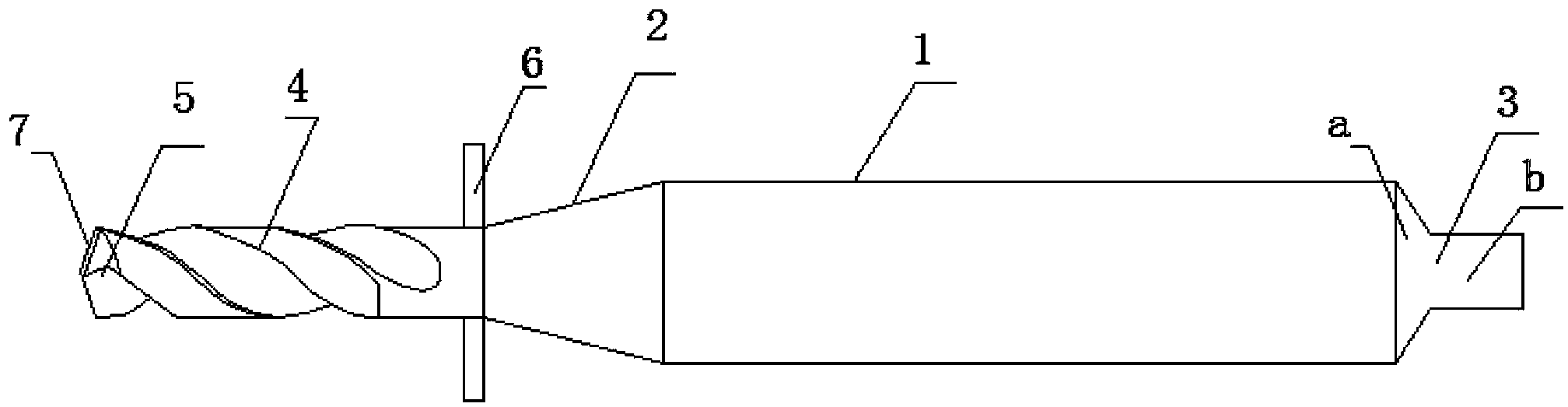
[0010] Such as figure 1 As shown, the welded alloy drill includes a drill shank 1. One end of the drill shank 1 is provided with a drill connecting portion 2, and the other end is provided with a drill positioning portion 3. The drill connecting portion 2 is welded with an alloy drill body 4, and the end of the alloy drill body A drill tip 5 is provided at the top of the drill bit, and a drill chip stopper 6 is provided on the peripheral surface of the joint 2 of the alloy drill body 4 and the drill bit joint.
[0011] An alloy blade 7 is arranged on the drill tip.
[0012] The drill positioning part is composed of a tapered part a and a cylindrical part b.
Login to View More PUM
 Abstract
The invention belongs to the field of drill bits and particularly relates to a welded alloy drill comprising a drill bit shank. A drill bit connecting portion is arranged at one end of the drill bit shank, a drill bit positioning portion is arranged at the other end of the drill bit shank, an alloy drill body is welded to the drill bit connecting portion, a drill point is arranged at the end of the alloy drill body, and drilling retaining plates are arranged on the peripheral surface of the joint of the alloy drill body and the drill bit connecting portion. The welded alloy drill has the advantages that drillings can be retained through the drillings retaining plates, and cost can be saved as the drill bit is welded.
Description
technical field [0001] The invention belongs to the field of drill bits, in particular to a welded alloy drill. Background technique [0002] A drill is a tool used to drill through holes or blind holes in solid materials and to ream existing holes. Commonly used drills mainly include twist drills, flat drills, center drills, deep hole drills and casing drills. The common drill bits currently in use are generally made of hard alloy and high-speed steel. Although the drill bit made of hard alloy material is durable, the price is very high, and the outer diameter of the drill bit produced will not exceed The cost of production and use is high. Although the drill bit made of high-speed steel is cheap and the cost of use is relatively low, because the drill bit of high-speed steel material is low in rigidity and easy to break, it is cumbersome to use and needs to be replaced frequently. Contents of the invention [0003] Aiming at the deficiencies in the above-mentioned tec...
Claims
Login to View More Application Information
Patent Timeline
 Patent Type & AuthorityApplications(China)
IPC IPC(8): B23B51/00
CPCB23B51/02B23B2222/28
Inventor包少毅
Owner常州耐尔特精密工具有限公司