Supercharge Your Innovation With Domain-Expert AI Agents!

Closed tank system

A fuel tank and tank body technology, applied in the direction of charging system, arrangement combined with internal combustion engine fuel supply, machine/engine, etc., can solve problems such as cost increase

Active Publication Date: 2015-02-11
TI AUTOMOTIVE TECH CENT
View PDF9 Cites 0 Cited by
  • Summary
  • Abstract
  • Description
  • Claims
  • Application Information

AI Technical Summary

Problems solved by technology

These larger vapor handling systems add weight and cost to the vehicle

Method used


Image

  • Closed tank system
  • Closed tank system
  • Closed tank system

Examples


Embodiment Construction

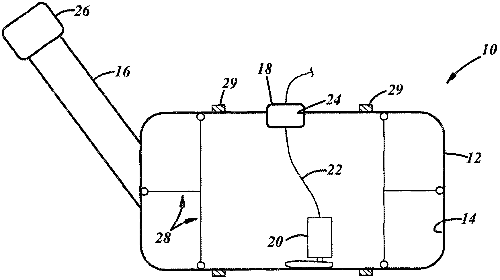
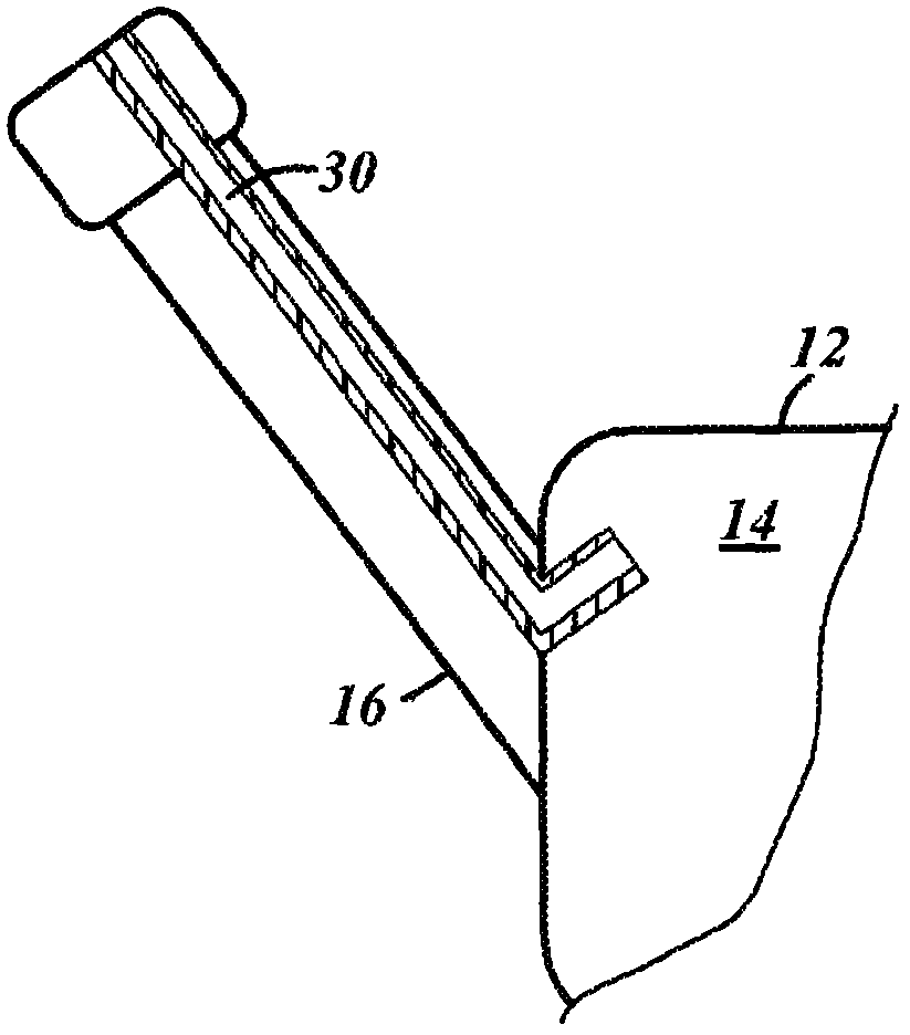
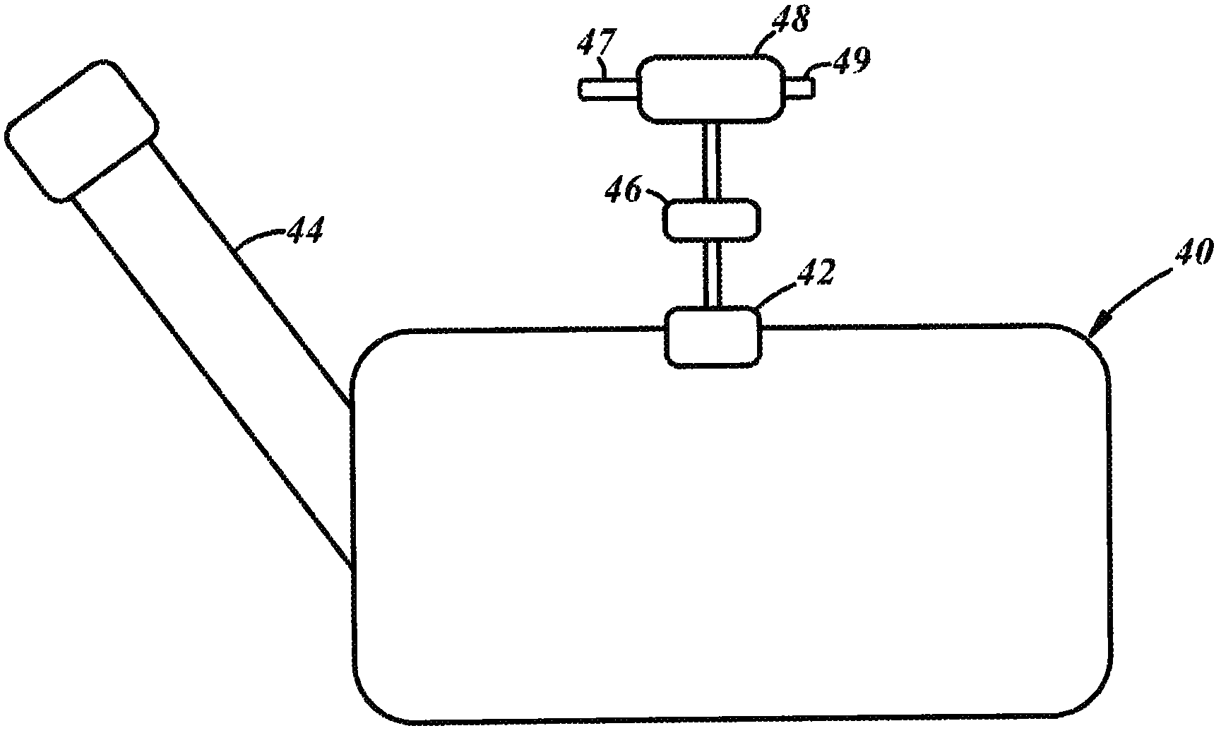
[0013] Referring to the accompanying drawings in more detail, figure 1 Shown is a vehicle fuel tank 10 designed to hold a volume of fuel to support operation of the vehicle engine. Fuel tank 10 may have a tank body 12 defining an interior chamber 14 in which fuel is received, and a fill tube 16 through which fuel is admitted into chamber 14 . If desired, an overpressure relief valve 18 may also be provided which only opens when the pressure in the fuel tank 10 is above a threshold level. A fuel pump 20, which may be located inside the fuel tank 10, or, if desired, external to the fuel tank, may receive fuel from the fuel tank chamber 14 and deliver it under pressure to fuel system components downstream of the fuel tank (e.g., fuel rails). and fuel injectors). Fuel pump 20 may be of conventional construction and arrangement and will not be discussed further. Output from fuel pump 20 may be provided through conduit 22 through fuel tank opening 24, preferably in the same area...


PUM


Abstract

In at least some implementations, a fuel tank (10, 40, 54) includes a tank body (12) defining a chamber (14) adapted to receive liquid fuel therein, a reinforcement for the tank body (12) to permit the pressure within the chamber (14) to exceed the vapor pressure of a fuel to be received within the chamber (14), and an inlet to the tank body (12) through which fuel is added to the chamber (14). The inlet is configured to mate with a refueling nozzle through which fuel is added to the chamber (14) to permit refueling the tank (10, 40, 54) and maintaining the pressure in the chamber (14) above atmospheric pressure.

Description

[0001] Cross References to Related Applications [0002] This application claims the benefit of US Provisional Application No. 61 / 861,187, filed August 1, 2013, and US Provisional Application No. 61 / 863,483, filed August 8, 2013, the entire contents of which are hereby incorporated by reference. technical field [0003] The present disclosure generally relates to vehicle fuel tanks. Background technique [0004] Many vehicles include a fuel tank that holds fuel that is ultimately supplied to a prime mover, like an internal combustion engine, to support the operation of the engine. In addition to holding fuel, fuel tanks typically house components within their interiors, such as pumps, valves, and the like. Also the fuel tank may be associated with a bulk vapor handling system including a large vapor tank to manage the fuel vapors generated within the tank (which are maintained at or very close to atmospheric pressure) and prevent fuel vapor from escaping to the atmosphere....

Claims


Application Information

Patent Timeline
IPC IPC(8): B60K15/03B60K15/04B60K15/01
CPCB60K2015/03296F02M25/089B60K2015/03217B60K15/04B60K15/03504B60K2015/03514B60K15/03177Y10T137/7287Y10T137/7837Y10T137/85954Y10T137/86043
Inventor A·J·贝克A·埃勒P·格米恩德P·格劳尔W·B·赫泽尔G·A·迈克利斯M·B·奥尔布里希
Owner TI AUTOMOTIVE TECH CENT
Features
  • R&D
  • Intellectual Property
  • Life Sciences
  • Materials
  • Tech Scout
  • Unparalleled Data Quality
  • Higher Quality Content
  • 60% Fewer Hallucinations
Learn More