Leftward and rightward movement receiving conveying system

A conveying system and material receiving technology, which is applied in the direction of conveyor objects, transportation and packaging, etc., can solve the problems of low work efficiency, high price and large volume, and achieve the effect of high work efficiency and high degree of automation.

Active Publication Date: 2015-02-11
GUANGDONG LONGXING PACKAGING IND
View PDF6 Cites 7 Cited by
  • Summary
  • Abstract
  • Description
  • Claims
  • Application Information

AI Technical Summary

Problems solved by technology

In this way, not only the work efficiency is low, but also there are potential safety hazards, and accidents are prone to occur.
However, there is no technology in the prior art that can well receive, store and transfer printed materials such as covers stacked in strips to the material inlet of the flat printing and capping equipment.
In the prior art, there is not only no transfer device dedicated to the transfer of flat stamping equipment, but also for the rotation of the heavier storage device, the rotary drive device in the prior art can either meet the lifting requirements but is expensive or bulky, or The price is reasonable but it is difficult to drive the heavy storage device to rotate, so it is impossible to smoothly transfer the printed materials such as covers stacked in strips in the storage device to the feed port of the flat stamping equipment

Method used


Image

  • Leftward and rightward movement receiving conveying system
  • Leftward and rightward movement receiving conveying system
  • Leftward and rightward movement receiving conveying system

Examples


Embodiment 1

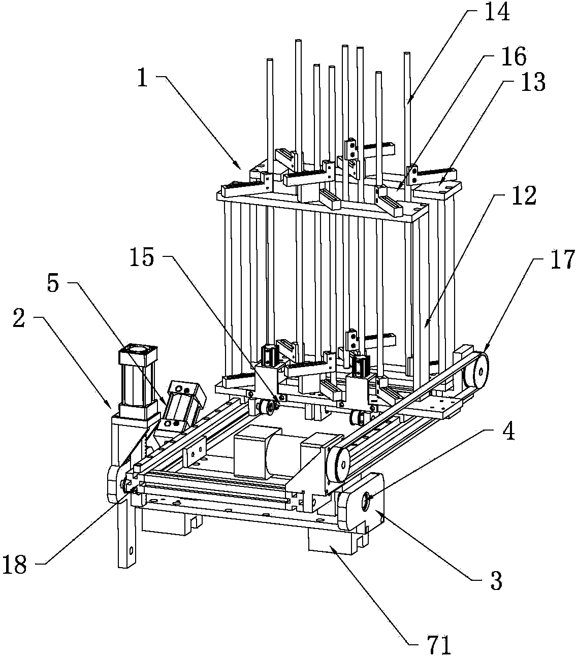
[0046] Such as figure 1 As shown, a material receiving and conveying device includes a support frame 3, a material receiving device 1, a rotating drive device 2, a rotating shaft 4 and a rotating auxiliary device 5, the rotating shaft 4 is rotatably installed on the supporting frame 3, and the rotating driving device 2 is installed on the support frame 3, the rotation driving device 2 is drivingly connected with the rotation shaft 4, and the material receiving device 1 is fixedly connected with the rotation shaft 4.

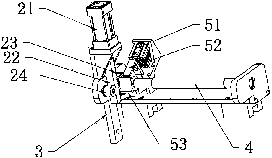
[0047]Such as figure 2 As shown, in this embodiment, the rotary driving device 2 includes a rotary cylinder 21, a rack 22, a gear 23 and a rack pinch wheel 24, the rotary cylinder 21 is installed on the support frame 3, and the rotary cylinder 21 and the rack 22 drive The rack 22 is engaged with the gear 23 for transmission, and the gear 23 is installed on the rotating shaft 4 . The rack pressing wheel 24 is rotatably mounted on the supporting frame 3 around i...

Embodiment 2

[0057] The main technical solutions of this embodiment are basically the same as those of Embodiment 1, and the features not explained in this embodiment are explained in Embodiment 1, and will not be repeated here. The difference between this embodiment and Embodiment 1 is that the two material receiving and conveying devices of a left-right shifting material receiving and conveying system in this embodiment share a set of discharging auxiliary devices.

Embodiment 3

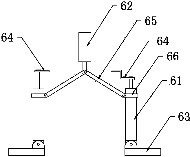
[0059] The main technical solutions of this embodiment are basically the same as those of Embodiment 1 or Embodiment 2, and the features not explained in this embodiment are explained in Embodiment 1 or Embodiment 2, and will not be repeated here. The difference between this embodiment and Embodiment 1 is that the number of lifting cylinders 61 of the receiving and conveying device of this embodiment is set to two, the number of clutch cylinders 62 is one, and the clutch cylinders 62 are located between the two lifting cylinders 61. In the middle, the piston rod of each lift cylinder 61 is provided with a bearing 64 .


PUM


Abstract

The invention discloses a leftward and rightward movement receiving conveying system, which comprises two receiving conveying devices, two sliding driving devices and sliding rails, wherein the sliding rails are fixedly arranged on a rack; sliding blocks arranged on the sliding rails in a sliding way are respectively and fixedly connected to support frames of the two receiving conveying devices; each receiving conveying device is driven by the corresponding sliding driving device to slide along the corresponding sliding rail in a reciprocating manner. The system also comprises a controller, wherein the two receiving conveying devices and the two sliding driving devices are electrically connected with the controller respectively; under the control of the controller, materials can be alternately conveyed by the two receiving conveying devices, and during the distribution conveying of one receiving conveying device, the other receiving conveying device is in a receiving state. The system has the advantages that (1) the automation degree is high; (2) materials subjected to printing are alternately conveyed by the left and right receiving conveying devices, so that the working efficiency is high; (3) labors are less in contact with the materials subjected to printing, so that higher safety and reliability are ensured.

Description

technical field [0001] The invention relates to the technical field of transporting plastic container lids stacked into strips of a convex plate plane capping machine, in particular to a left and right shifting transmission system of a plane plane capping machine. Background technique [0002] For flat plastic substrates such as covers, it is usually necessary to use a special flat-bed offset printing machine, while the current mainstream flat printing and capping equipment feeds the inlet on the upper surface of the flat printing and capping equipment, and the position is relatively high. When adding substrates, In the prior art, the worker sits on a high stand and manually transfers the stacks of covers and other substrates to the material inlet, and puts the stacked strips of substrates such as covers vertically into the feeding material of the flat printing and capping equipment. mouth. In this way, not only the work efficiency is low, but also there are potential safet...

Claims


Application Information

Patent Timeline
Patent Type & Authority Applications(China)
IPC IPC(8): B65G47/10
Inventor 王昌佑
Owner GUANGDONG LONGXING PACKAGING IND
Why Eureka
Try Eureka