
MEMS (micro-electromechanical system) circuit cover and manufacturing method thereof

A manufacturing method and lid technology, which are applied to circuits, electrical components, electrical solid devices, etc., can solve problems such as affecting processing efficiency, improving packaging cost, dimensional accuracy, consistency and surface finish, etc., to improve production efficiency and reduce Production labor cost and the effect of improving production efficiency

Active Publication Date: 2015-02-11
WUXI CHINA RESOURCE MICRO ASSEMBLY TECH
View PDF9 Cites 2 Cited by
  • Summary
  • Abstract
  • Description
  • Claims
  • Application Information

AI Technical Summary

Problems solved by technology

Therefore, in the prior art, the capping process of MEMS pressure sensors with caps is a semi-automatic process, which requires manual participation in sorting the aluminum caps into the carrier. On the one hand, the packaging cost is increased, and each capping machine needs to be equipped with a separate Sorting personnel, on the other hand, cannot realize automatic capping, which affects processing efficiency and increases the possibility of personnel misoperation
[0004] In addition, because the cover used in the current MEMS pressure sensor circuit is machined from aluminum sheets, it is lacking in dimensional accuracy, consistency and surface finish. At the same time, there is a problem of clogging of processing residues in the small vent hole during processing, which affects the Yield rate of MEMS products

Method used


Image

  • MEMS (micro-electromechanical system) circuit cover and manufacturing method thereof
  • MEMS (micro-electromechanical system) circuit cover and manufacturing method thereof
  • MEMS (micro-electromechanical system) circuit cover and manufacturing method thereof

Examples


Embodiment 1

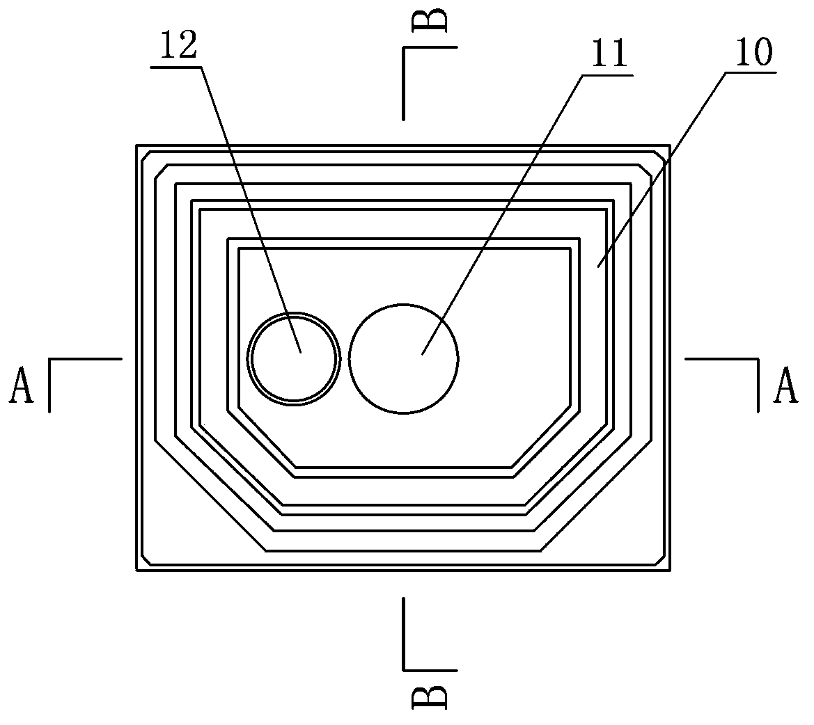
[0028] Embodiment one: see Figure 1-6 As shown, a MEMS circuit cover includes a cover body 10 injection-molded by epoxy resin, a support point 11 is provided in the middle of the cover body 10 , and a vent hole 12 is provided on one side of the support point 11 .

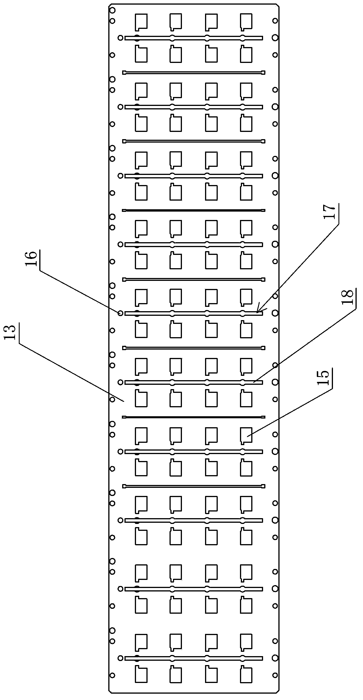
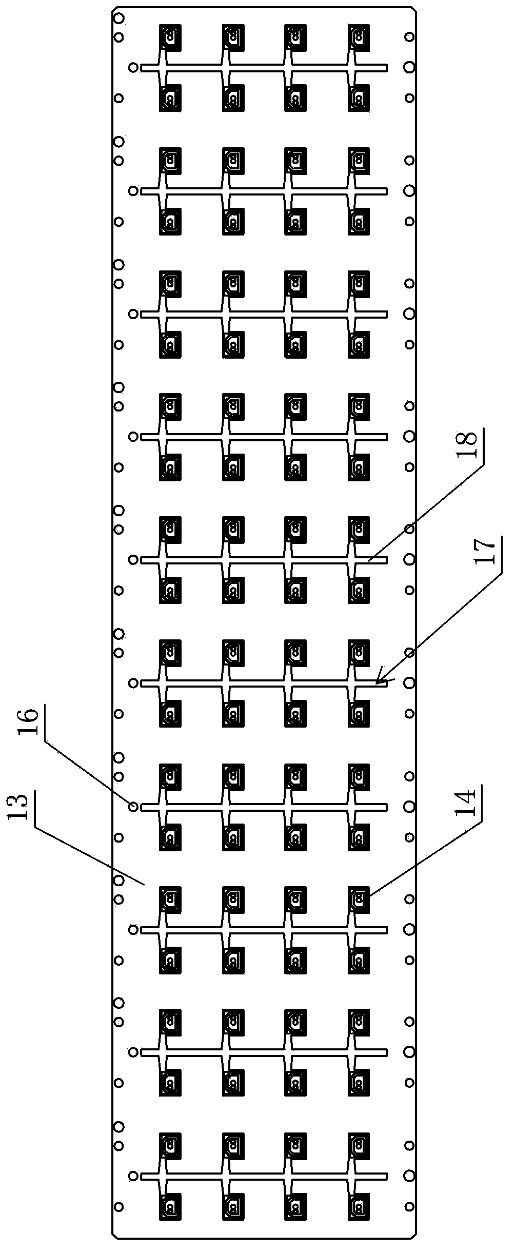
[0029] The method for making the above-mentioned MEMS circuit cover is: comprising a frame carrier 13 and a plastic sealing mold, the frame carrier 13 is provided with several vacancies 15 matching the size of the cover 14, and the plastic sealing mold includes several mold boxes, each mold At least one frame carrier 13 can be accommodated in the box, and the mold box is respectively provided with a cavity corresponding to each vacancy 15 on the frame carrier 13, and the shape of the cavity matches the shape of the cover 14. The steps are: first place the frame carrier 13 in the mold box, make the vacancy 15 correspond to the position of the cavity, then close the plastic sealing mold, inject the epoxy resin soluti...


PUM


Abstract

The invention discloses an MEMS (micro-electromechanical system) circuit cover and a manufacturing method thereof. The MEMS circuit cover comprises a cover body formed by injection molding of epoxy resin, wherein a supporting point is arranged in the middle of the cover body and a vent hole is formed in one side of the supporting point. According to the manufacturing method, frame carriers and a plastic seal mould are used; a plurality of vacancies matched with covers in size are arranged on the frame carriers; the plastic seal mould comprises a plurality of mould boxes; the at least one frame carrier can be accommodated in each mould box; holes are formed in the parts of the mould boxes, corresponding to the vacancies on the frame carriers and are matched with the covers in shape. The manufacturing method comprises the following steps: firstly, putting the frame carriers into the mould boxes and enabling the vacancies to correspond to the holes in position; secondly, closing the plastic seal mould, filling the mould boxes with an epoxy resin solution, and filling up all the holes; finally, opening the plastic seal mould and taking out the frame carriers with the covers, so that the operation of manufacturing the covers is finished. Therefore, a full-automatic cover mounting process can be performed, the production efficiency is improved, and the cost is reduced.

Description

technical field [0001] The invention relates to the technical field of semiconductor packaging, in particular to the improvement of a MEMS pressure sensor circuit cover structure and manufacturing method, so as to realize the automatic cover production process. Background technique [0002] The basic process of common MEMS pressure sensor circuit processing is: installing chips in the pre-plastic casing, bonding-pointing protective glue in the casing-covering-printing and cutting and bending the pins. [0003] The existing MEMS pressure sensor circuit cover basically adopts an aluminum cover, and the processing method of the aluminum cover: the aluminum plate is cut into aluminum sheets of a specified size (square or rectangular) by mechanical processing, and a small hole is punched on each aluminum sheet (mainly for ventilation) , connected to the atmospheric pressure), the processed aluminum sheets with small holes are stacked together, and hundreds or thousands of aluminu...

Claims


Application Information

Patent Timeline
IPC IPC(8): B81B7/00B29C45/14B29C45/78B29C45/26
Inventor 龚平刘晓明韩林森王从亮
Owner WUXI CHINA RESOURCE MICRO ASSEMBLY TECH
Learn More