
Centrifugal air blower and vehicle-mounting air-conditioning apparatus comprising same

A technology of air blower and centrifugal fan, which is applied in the field of centrifugal air blower and vehicle air conditioner to achieve the effect of reducing friction

Active Publication Date: 2015-02-11
三电株式会社
View PDF6 Cites 13 Cited by
  • Summary
  • Abstract
  • Description
  • Claims
  • Application Information

AI Technical Summary

Problems solved by technology

In the centrifugal blower described above, compared with the centrifugal blower disclosed in Patent Document 1, although the concentration of the flow of air discharged from the blades to the lower plate side is improved, it still concentrates in the direction of the lower plate side.

Method used


Image

  • Centrifugal air blower and vehicle-mounting air-conditioning apparatus comprising same
  • Centrifugal air blower and vehicle-mounting air-conditioning apparatus comprising same
  • Centrifugal air blower and vehicle-mounting air-conditioning apparatus comprising same

Examples


Embodiment Construction

[0055] Hereinafter, embodiments of the present invention will be described with reference to the drawings.

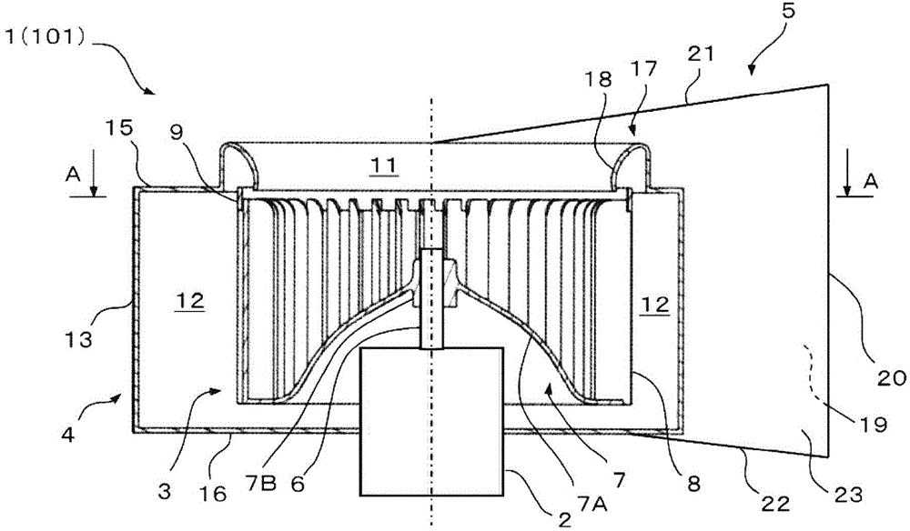
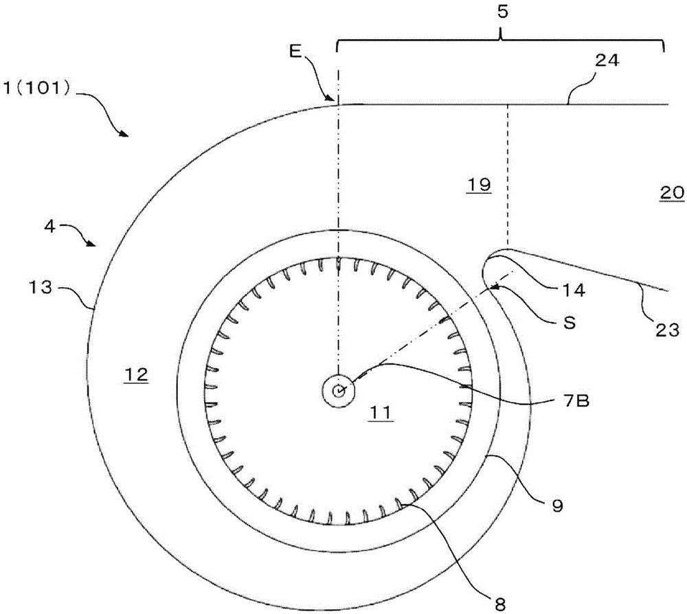
[0056] figure 1 A longitudinal sectional view showing the centrifugal blower 1 according to the first embodiment of the present invention. figure 2 yes figure 1 The A-A line shown is the sectional view.

[0057] The centrifugal blower 1 of the present embodiment includes an electric motor 2 as a driving element, a multi-blade centrifugal fan 3 driven to rotate by the electric motor 2 , a scroll casing 4 , and a diffuser portion 5 .

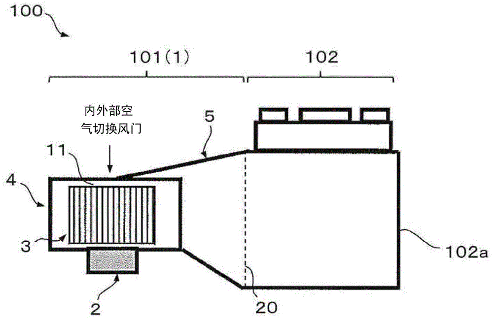
[0058] Such as image 3 As shown, the centrifugal blower 1 of this embodiment is used, for example, as the blower unit 101 of the vehicle air conditioner 100 , and the centrifugal blower 1 is arranged between an inside and outside air switching damper (not shown) and a temperature adjustment unit 102 .

[0059] The electric motor 2 has a shaft 6 connected to a later-described protrusion 7B of the multi-blade centrifugal fan 3 , and r...


PUM


Abstract

A centrifugal air blower and vehicle-mounting air-conditioning apparatus capable of improving air flow amount. The centrifugal blower (1) comprises: a multifin centrifugal fan (3), having a plurality of blades (8) arranged around a rotating shaft (6); a scroll-shaped casing (4) accommodating the centrifugal fan (3) and having an air suction inlet (11) and a flow passage vortex-shaped flow path (12) as a flow path for air from multiple fins centrifugal fan exhaust air; and a diffuser portion (5), which has a expanded stream path (19) and an outlet (20), wherein the downstream end of the vortex-shaped flow path (12) is communiated with the expanded stream path (19), and changes the height of the flow path in a manner of the cross-sectional area increasing with downstream side of the air flow. The outlet is opened at the downstream of the expanded stream path. The centrifugal blower is provided with multiple fins from centrifugal fan exhaust air flow rate uniform distribution of the upstream distribution equalizing element (18), wherein the upper side wall (21) of the diffuser portion of the inclined starting position than the lower side wall disposed in the diffuser portion (22) is inclined starting position closer to the air flow position side.

Description

technical field [0001] The present invention relates to a centrifugal blower and a vehicle air conditioner including the centrifugal blower, and more particularly, to a centrifugal blower and a vehicle air conditioner in which the shape of a diffuser portion of the centrifugal blower is improved. Background technique [0002] This centrifugal blower accommodates a multi-blade centrifugal fan in a volute casing, and the multi-blade centrifugal fan has many blades arranged around a rotating shaft. A vortex flow path is formed. When the multi-blade centrifugal fan is driven to rotate by a driving source such as an electric motor, the air is sucked into the inner side of the multi-blade centrifugal fan from the suction port formed in the scroll casing, and the air is discharged into the multi-blade centrifugal fan. The air is blown out from the air outlet formed on the downstream side of the air flow through the scroll-shaped flow path on the radially outer side of the fan. ...

Claims


Application Information

Patent Timeline
IPC IPC(8): F04D29/30F04D29/44
CPCF04D29/4206F04D29/441
Inventor 川埼真俊野村梨纱
Owner 三电株式会社
Learn More