Volute tongue structure of fan for range hood

A technology for range hoods and fans, which is applied to components of pumping devices for elastic fluids, machines/engines, mechanical equipment, etc., can solve the problems of generating vortices, the overall efficiency of fans cannot be improved, and noise reduction, etc. The effect of overall efficiency

Active Publication Date: 2015-02-11
NINGBO FOTILE KITCHEN WARE CO LTD
View PDF7 Cites 9 Cited by
  • Summary
  • Abstract
  • Description
  • Claims
  • Application Information

AI Technical Summary

Problems solved by technology

In this way, when the impeller rotates under the action of the motor, the air in the volute is discharged out of the volute by the impeller, forming a negative pressure in the volute, and the oil fume enters the suction port under the action of negative pressure, and is discharged from the volute under the action of the impeller. Outside the shell, the disadvantage of the volute of this range hood is that the airflow in the volute is noisy
[0004] In order to reduce the noise of the fan and eliminate the vortex, people have improved the structure of the volute tongue, as disclosed in the Chinese invention patent application with the application number 201110427490. The range hood of the fan" forms a concave part on the volute tongue part of the scroll case to the outside of the scroll case, so that the concave part is arc-shaped from the direction of the air outlet. The air flow is rectified to reduce the noise generated at the volute tongue when the range hood is working, but the gap between the lower end surface of the volute tongue and the impeller is the same, so the fan is easy to generate vortices on the front and rear sides of the volute tongue when it is working
[0005] Another e

Method used


Image

  • Volute tongue structure of fan for range hood
  • Volute tongue structure of fan for range hood
  • Volute tongue structure of fan for range hood

Examples


Embodiment Construction

[0021] The present invention will be further described in detail below in conjunction with the accompanying drawings and embodiments.

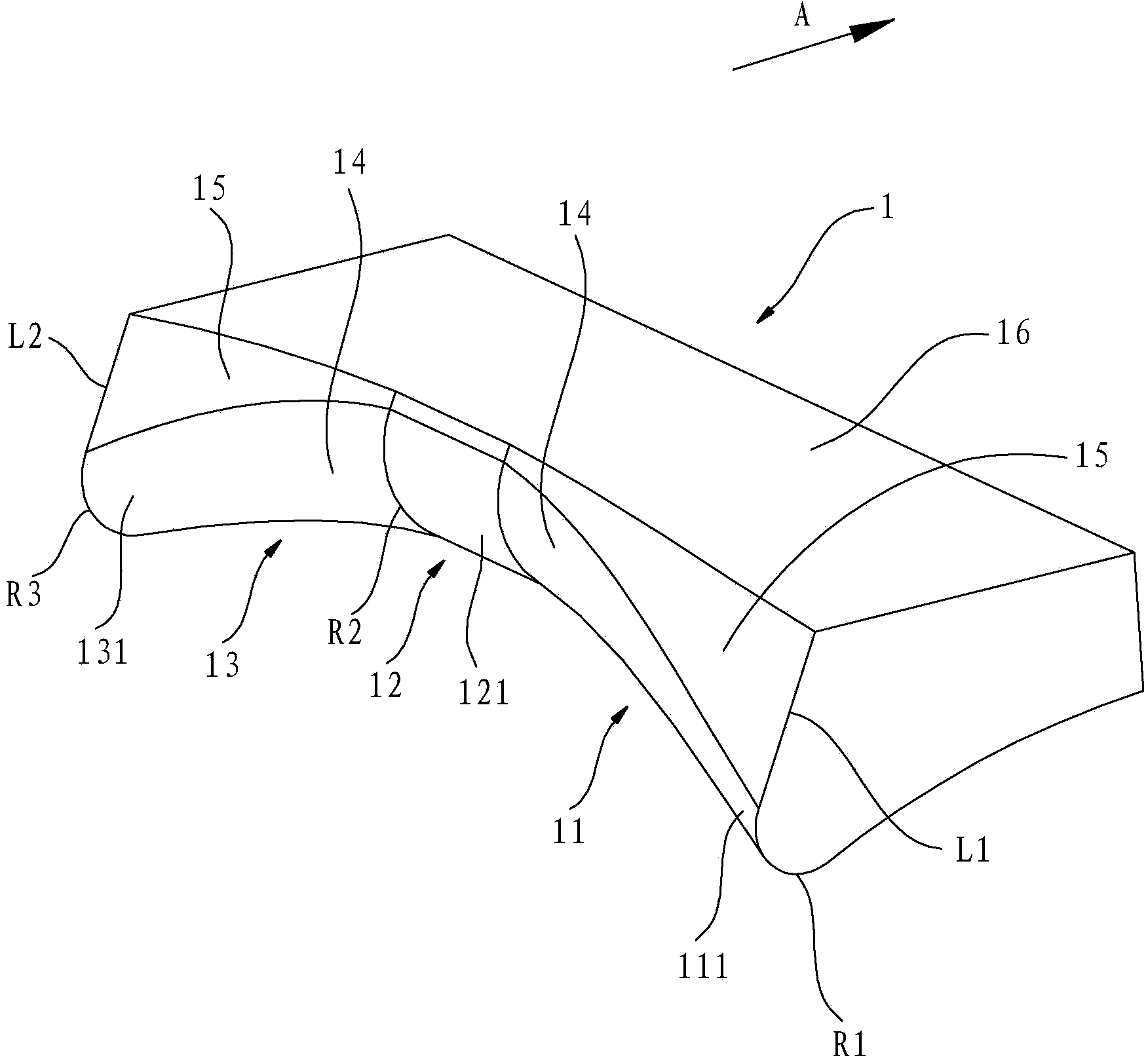
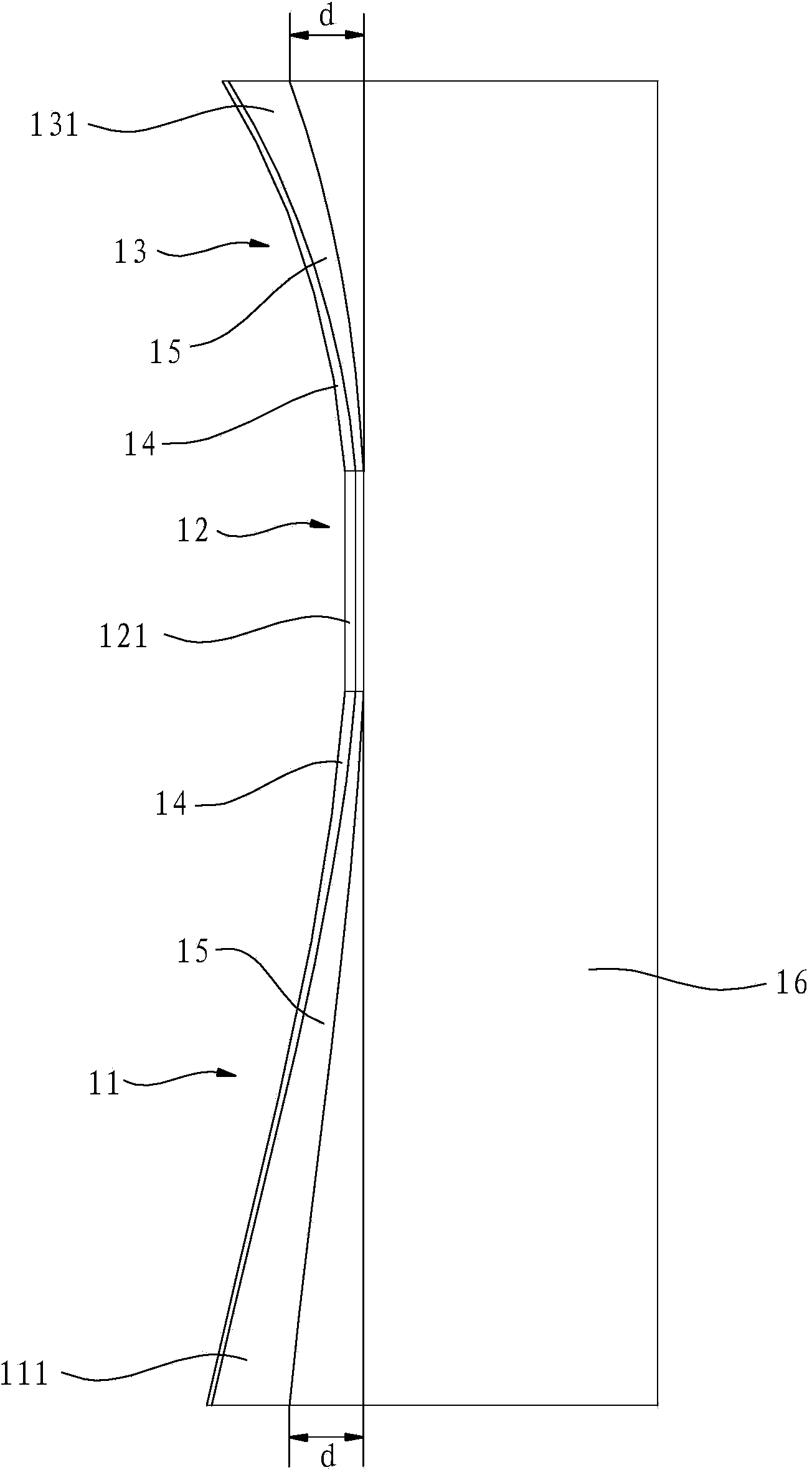
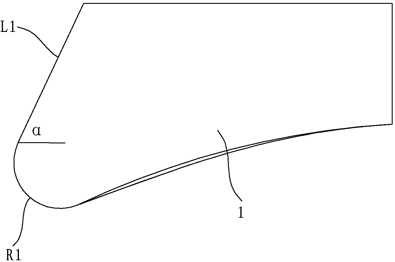
[0022] Such as Figure 1 to Figure 3 As shown, the volute tongue in this embodiment has a front plate 11, a middle plate 12 and a rear plate 13, and the front plate 11, the middle plate 12 and the rear plate 13 are integrally formed parts. Refer to the comparative document with the title of the invention "Range Hood and Its Volute Case and Volute Tongue" (Application No. 201210210890.X (Application Publication No. 103512064 A)), the volute tongue of the comparative document is on the side facing the air outlet of the fan has an inner concave surface to figure 1 The direction shown by the straight arrow A is right. Assuming that the volute tongue in this embodiment has the inner concave surface shown in the above-mentioned reference document, the front plate 11 extends to the lower left corner to form a front deep tongue 111, and the rear plat...


PUM


Abstract

The invention relates to a volute tongue structure of a fan for a range hood. An inner concave surface is formed on one side, facing an air outlet of the fan, of a volute tongue. The volute tongue structure is characterized in that the volute tongue comprises a front disk, a central disk and a rear disk, wherein the side parts, facing to the air outlet of the fan, of the front disk, the central disk and the rear disk wholly form the inner concave surface, the front disk further extends to the bottom left to form a front side deep tongue on the basis of the inner concave surface, the rear disk further extends to the bottom left to form a rear side deep tongue on the basis of the inner concave surface, and the central disk is continuously and inwards concave to form a central short tongue on the basis of the inner concave surface. Compared with the prior art, the volute tongue structure disclosed by the invention has the advantages that the volute tongue forms the front side deep tongue, the rear side deep tongue and the central short tongue, the gap between the front disk, the rear disk and a vane wheel is smaller, and the gap between the central disk and the vane wheel is larger, so that the speed at which front and back air currents flow out cannot be much lower than the speed at which the central air current flows out, the whirlpool caused by a low speed of two sides and high speed of the center is eliminated, and further the whole efficiency of the fan is improved.

Description

technical field [0001] The invention relates to a range hood, in particular to a fan volute tongue structure used for the range hood. Background technique [0002] Range hoods have become one of the essential kitchen equipment for ordinary families. The noise of range hoods generally comes from two aspects: one is the noise of the fan itself, and the other is the noise caused by the airflow flowing in the fan volute. The volute of the range hood includes a volute case, a volute tongue, an air outlet and an air suction port. The side plate is composed of side plates, the left and right side plates are installed on both sides of the volute casing cladding plate to form a spiral disk body, there is a suction port on the side of the volute case, and an impeller and a volute tongue are arranged inside the volute case corresponding to the position of the suction port. It is located at the starting position of the thread of the volute case, and the air outlet is located at the end...

Claims


Application Information

Patent Timeline
IPC IPC(8): F04D29/42F04D29/66
CPCF04D29/422F04D29/668
Inventor 何立博叶丰徐群浪茅忠群诸永定王军元
Owner NINGBO FOTILE KITCHEN WARE CO LTD
Why Eureka
Try Eureka