Chain guide mechanism

一种引导机构、链条的技术,应用在皮带/链条/齿轮、机械设备、传动装置等方向,能够解决链条啮合音、油压保持功能受损、张紧器T的构成部件磨损等问题,达到平滑链条行进、抑制异响产生、维持链条张力的效果

Inactive Publication Date: 2015-02-11
TSUBAKIMOTO CHAIN CO
View PDF7 Cites 3 Cited by
  • Summary
  • Abstract
  • Description
  • Claims
  • Application Information

AI Technical Summary

Problems solved by technology

[0010] That is, in the case of using the hydraulic tensioner T, much processing is required on the engine side such as the engine side oil passage, so the cost increases.
In addition, in order to supply oil to the hydraulic tensioner T, it is necessary to increase the output of the oil pump (not shown), resulting in high friction
In addition, when the engine is started, there is a time lag from the start of the engine to the supply of oil pressure to the hydraulic tensioner T, and abnormal noise is likely to occur due to this time lag.
In addition, if the oil pressure supplied from the oil pump is too high, the chain meshing sound and friction will deteriorate; on the other hand, if the oil pressure supplied from the oil pump is too low, chattering sound and abnormal noise of the chain CH will be generated.
In addition, when foreign matter is mixed into the engine lubricating oil, clogging is likely to occur in the hydraulic tensioner T, and as a result, the hydraulic pressure maintenance function is impaired, and abnormalities such as engine noise are likely to occur.
In addition, when the engine lubricating oil is deteriorated, the components of the tensioner T are worn, and as a result, the oil pressure holding function is impaired, and abnormalities such as engine noise are likely to occur.
In addition, a ratchet (not shown) that restricts the travel of the plunger T1 has been provided in the hydraulic tensioner T in order to reduce the abnormal noise when the engine is started. problems such as chain meshing sound, friction deterioration, etc.

Method used


Image

  • Chain guide mechanism
  • Chain guide mechanism
  • Chain guide mechanism

Examples


Embodiment Construction

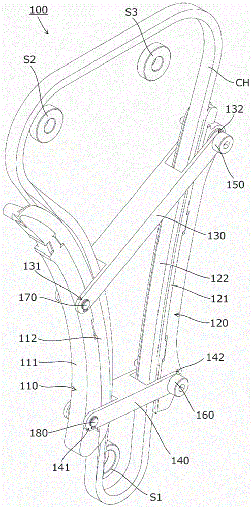
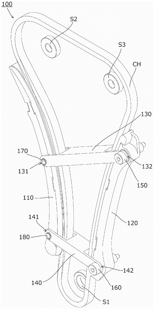
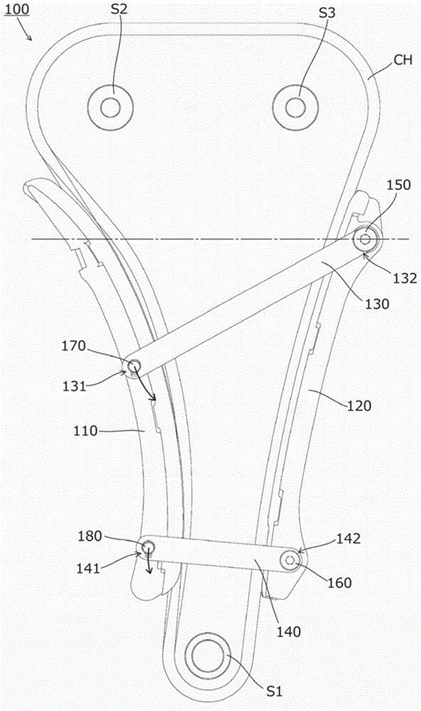
[0034]The present invention is a chain guide mechanism for guiding a chain. As long as it conforms to the following description, its specific structure can be any structure, that is, the chain guide mechanism has: a slack side guide, which is arranged on the slack side of the chain travel route; The guide is arranged on the tension side of the chain travel path; and the connecting member is rotatable around a predetermined rotation axis, the above-mentioned rotation shaft is provided in a fixed state on the installation object of the chain guide mechanism, and the connecting member has a rotatable installed on the slack-side pivot portion of the slack-side guide in such a way that the slack-side pivot portion is arranged on the opposite side of the prescribed rotation axis across the chain guided by the slack-side guide, and is arranged lower than the prescribed rotation axis. The position of the slack side guide is biased towards the side of the chain guided by the slack side ...


PUM


Abstract

The chain guide mechanism includes a slack side guide, a tension side guide, and a link member that is capable of rotating about a predetermined rotary shaft provided so as to be fixed to an attachment subject. The link member includes a slack side pivot portion attached rotatably to the slack side guide, and the slack side pivot portion is disposed on an opposite side of the chain that is guided by the slack side guide to the predetermined rotary shaft, and in a lower position than the predetermined rotary shaft. The slack side guide is biased by its own weight toward a side of the chain that is guided by the slack side guide.

Description

technical field [0001] The present invention relates to a chain guide mechanism for guiding a chain, and more particularly to a chain guide mechanism for a timing system. Background technique [0002] Conventionally, a chain guide mechanism for a timing system is known, which is installed in the engine compartment of an automobile, slides and guides a chain running between sprockets, and maintains the tension of the chain appropriately (for example, refer to Patent Document 1). . [0003] Such as Figure 11 As shown, the chain guide mechanism 500 includes: a slack side guide (swing guide) 510, which is swingably attached to an engine block (not shown) as an attachment target on the slack side of the chain travel path; and The tension side guide (fixed guide) 520 is fixed to the engine block on the tension side of the chain travel path. [0004] prior art literature [0005] patent documents [0006] Patent Document 1: Japanese Patent Application Laid-Open No. 10-89428 ...

Claims


Application Information

Patent Timeline
Patent Type & Authority Applications(China)
IPC IPC(8): F16H7/18F16H7/08
CPCF16H2007/185F16H7/18F16H7/08F16H2007/0821F16H2007/0874F16H2007/0893
Inventor 榑松勇二
Owner TSUBAKIMOTO CHAIN CO
Why Eureka
Try Eureka