
Freeze protection check valve for liquid delivery pipeline

A technology for conveying pipelines and check valves, applied in the field of antifreeze check valves, can solve problems such as affecting production efficiency, and achieve the effect of ensuring work efficiency

Active Publication Date: 2015-02-11
FUJIAN SOUTHERN HIGHWAY MECHANICAL
View PDF6 Cites 5 Cited by
  • Summary
  • Abstract
  • Description
  • Claims
  • Application Information

AI Technical Summary

Problems solved by technology

But this kind of check valve is only suitable for emptying the liquid in the pipeline when there is no production for a long time. In summer or when the construction period is busy and continuous production is required, this kind of check valve will affect the production efficiency and has certain limitations. Therefore, still needs to be improved

Method used


Image

  • Freeze protection check valve for liquid delivery pipeline
  • Freeze protection check valve for liquid delivery pipeline
  • Freeze protection check valve for liquid delivery pipeline

Examples


Embodiment 1

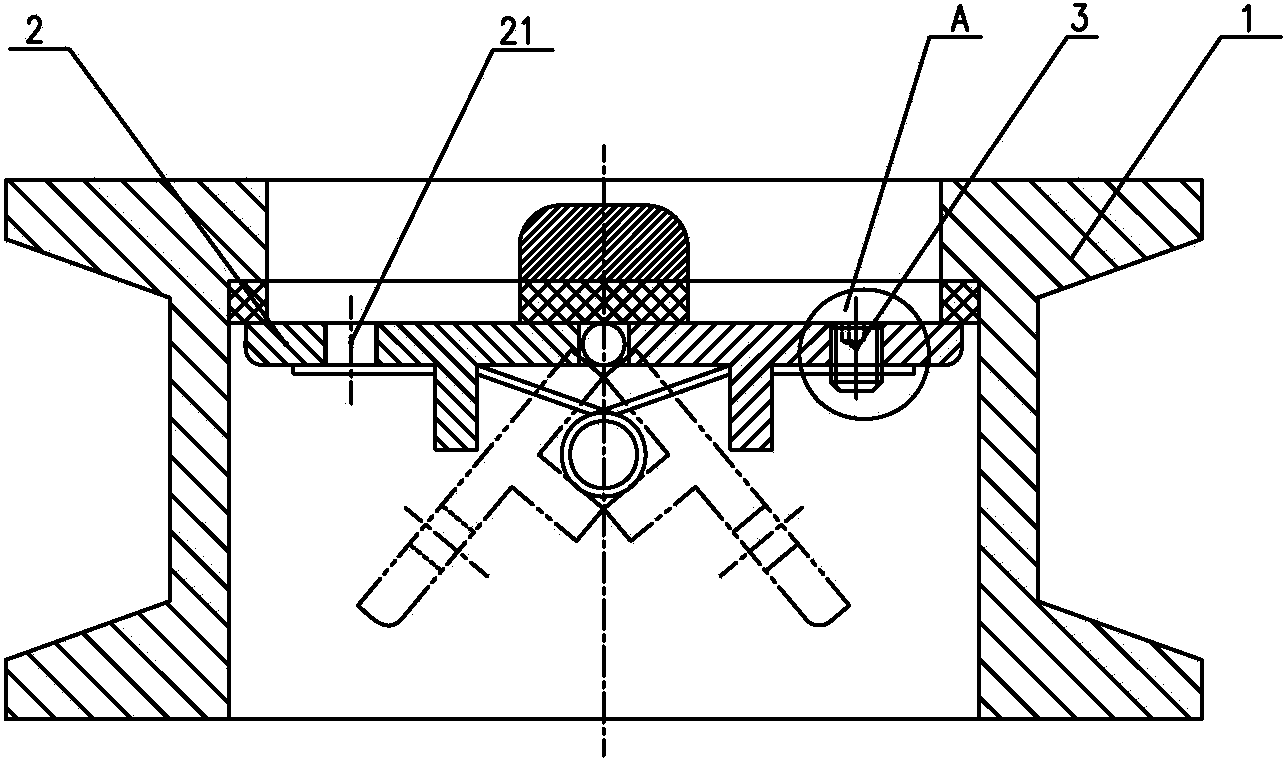
[0029] refer to figure 1 , Figure 4 As shown, the plugging device 3 is a bolt compatible with the thread of the damping hole 21, and when the damping hole needs to be blocked, the check valve is removed, and the blocking hole is blocked with the plugging device.

Embodiment 2

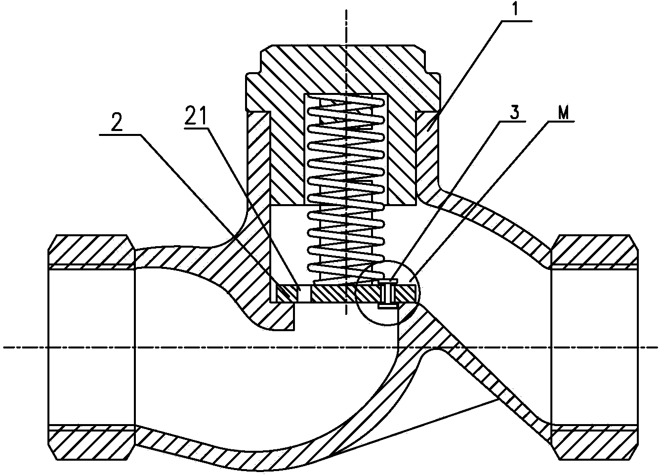
[0031] refer to figure 2 , Figure 5 As shown, the plugging device 3 is an "I" structural member made of a material with a volume expansion coefficient greater than 50%. The middle part of the plugging device 3 is stuck in the damping hole 21, and the diameter of both ends is larger than the damping hole. 21 diameter, so that the member cannot escape from the damping hole. Due to the volume shrinkage at low temperature, the diameter of the middle part will be smaller than the diameter of the damping hole. There is an obvious gap between the damping hole and the structure, and the damping hole is in a connected state. When the diameter of the middle part of the structure is equivalent to the diameter of the damping hole, there is basically no gap between the plugging structure and the damping hole, and the damping hole is blocked. When the temperature is higher, the volume expansion of the plugging structure is greater, and the damping hole is completely blocked. The structu...

Embodiment 3

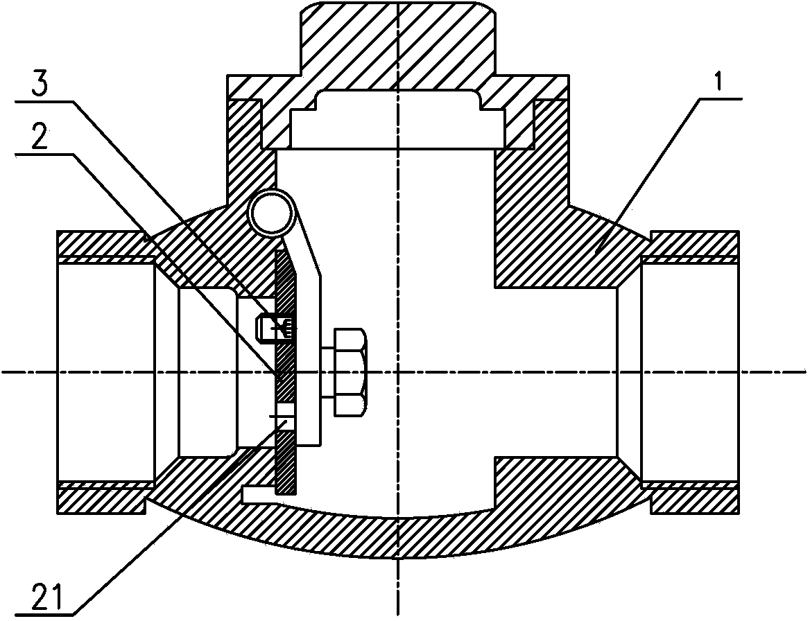
[0033] refer to Image 6 , 7 As shown, the plugging device 3 includes a cover piece 311 and a rotating shaft 312. The cover piece 31 is assembled on the valve flap 2 through the rotating shaft 32. The cover piece 31 can rotate relative to the valve flap 2, and the different orientations of the cover piece 31 are rotated to realize alignment. The closure and communication of the damping hole 21.


PUM


Abstract

The invention relates to the technical field of valve control in fluid delivery, in particular to a freeze protection check valve for a liquid delivery pipeline. The freeze protection check valve for the liquid delivery pipeline comprises a valve body, and a valve clack and a hole plugging device which are arranged in the valve body; the valve clack is provided with a plurality of damping holes; the hole plugging device is arranged on the valve clack and is not interfered with the opening and closing of the valve clack; the hole plugging device is matched with the damping holes and can seal the damping holes if necessary. When the check valve is in a low temperature working condition, open damping holes can enable liquid from the check valve to a water tank pipeline to slowly flow through the damping holes to flow back, and the pipeline is prevented from being subjected to frost cracking due to long-term liquid storage; continuous production is required in summer or in busy times, the damping holes are sealed by the hole plugging device and the on / off states of the damping holes in the valve clack are changed through the hole plugging device, so that working efficiency is ensured, different functions of the check valve are realized, and different working condition requirements are met.

Description

technical field [0001] The invention relates to the technical field of valve control in fluid delivery, in particular to an antifreeze check valve used in liquid delivery pipelines. Background technique [0002] The liquid supply system with a pump is a commonly used pipeline system in production and life. The backflow of liquid in the pipeline will cause the pump set to reverse, which will affect the service life of the pump and motor. In addition, the violent backflow of liquid will also cause pipeline vibration. In order to prevent the violent backflow of pipeline liquid, a check valve is usually installed at the outlet of the pump, but the check valve will cause the liquid in the main pipeline to be stored in the pipeline for a long time. In winter in the north, the liquid stored in the pipeline for a long time It will cause the pipeline to freeze and crack. Traditionally, in order to prevent the pipeline from freezing and cracking, a drain ball valve can be installed a...

Claims


Application Information

Patent Timeline
Patent Type & Authority Applications(China)
IPC IPC(8): F16K15/03F16K15/06F16K1/32
CPCF16K1/32F16K15/03F16K15/063
Inventor 罗其钢温士俊陈杰河
Owner FUJIAN SOUTHERN HIGHWAY MECHANICAL
Learn More