Heat exchanger and manufacturing method thereof

A processing method and technology of heat exchangers, applied in the direction of heat exchanger types, indirect heat exchangers, heat exchange equipment, etc., can solve problems such as bad heat exchangers, difficult to control the bending size, and strained fins, etc., to achieve Good processing effect

Inactive Publication Date: 2015-02-11
SANHUA HANGZHOU MICRO CHANNEL HEAT EXCHANGER
View PDF3 Cites 5 Cited by
  • Summary
  • Abstract
  • Description
  • Claims
  • Application Information

AI Technical Summary

Problems solved by technology

However, from the drawing of the design, the middle part will protrude from the heat exchanger after bending, and the bending size is difficult to control
More importantly, in the actual processing process, if t

Method used


Image

  • Heat exchanger and manufacturing method thereof
  • Heat exchanger and manufacturing method thereof
  • Heat exchanger and manufacturing method thereof

Examples


Embodiment Construction

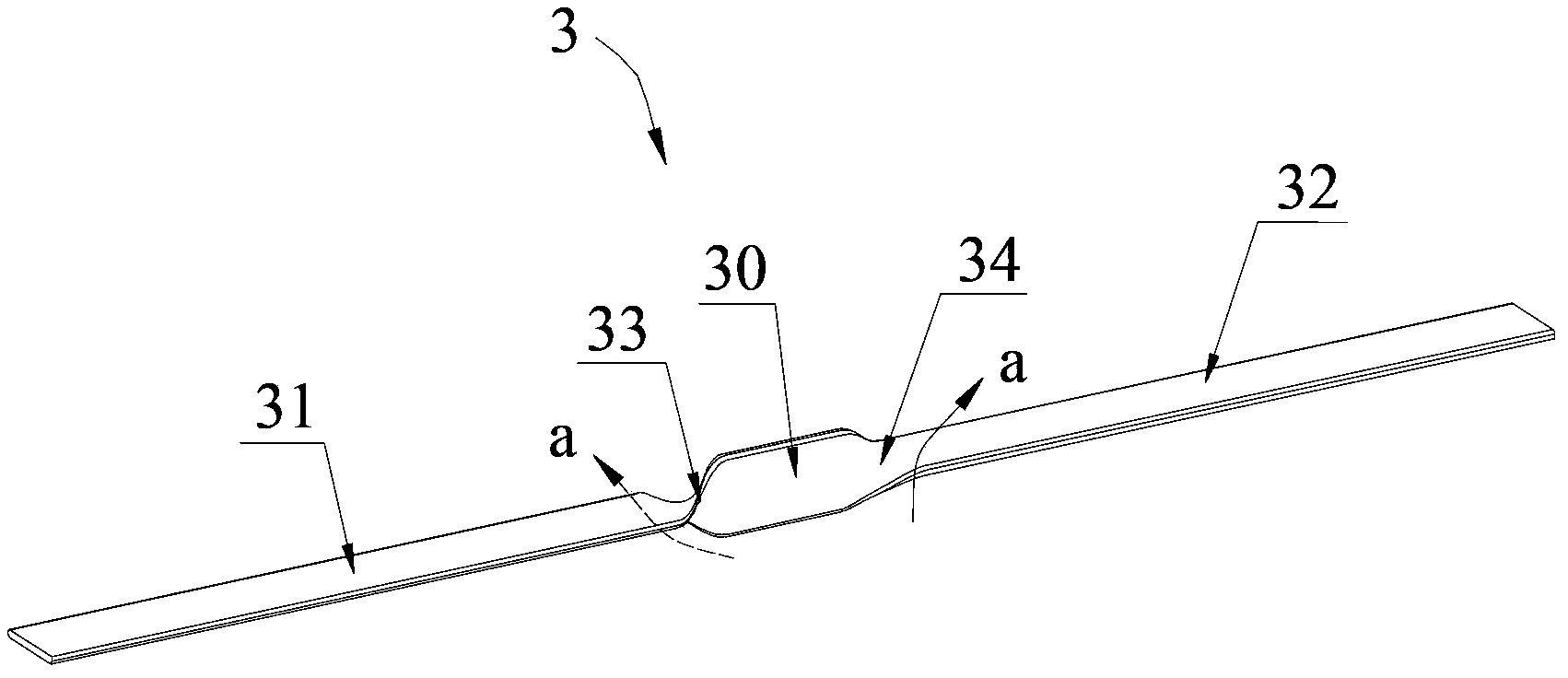
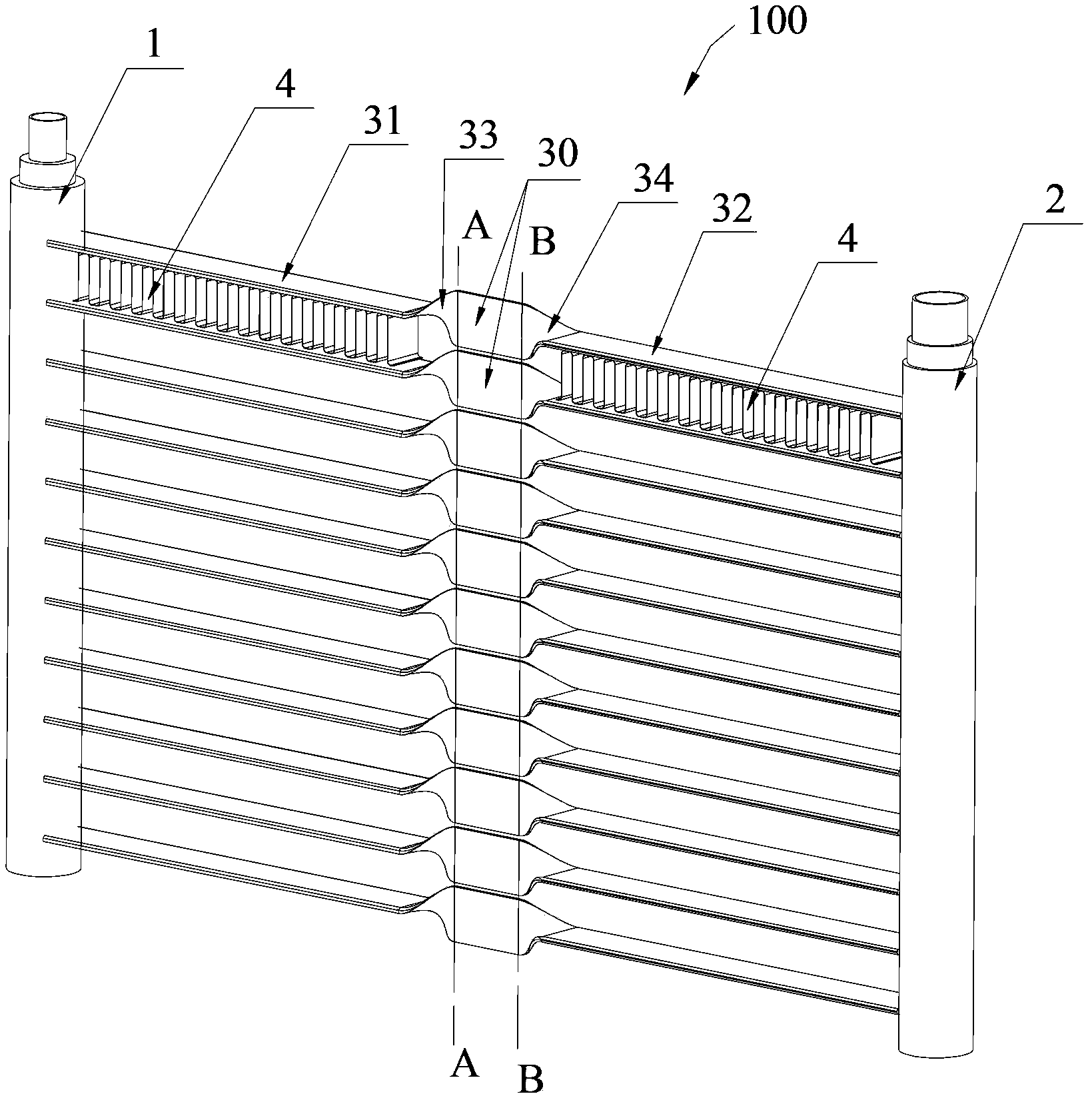
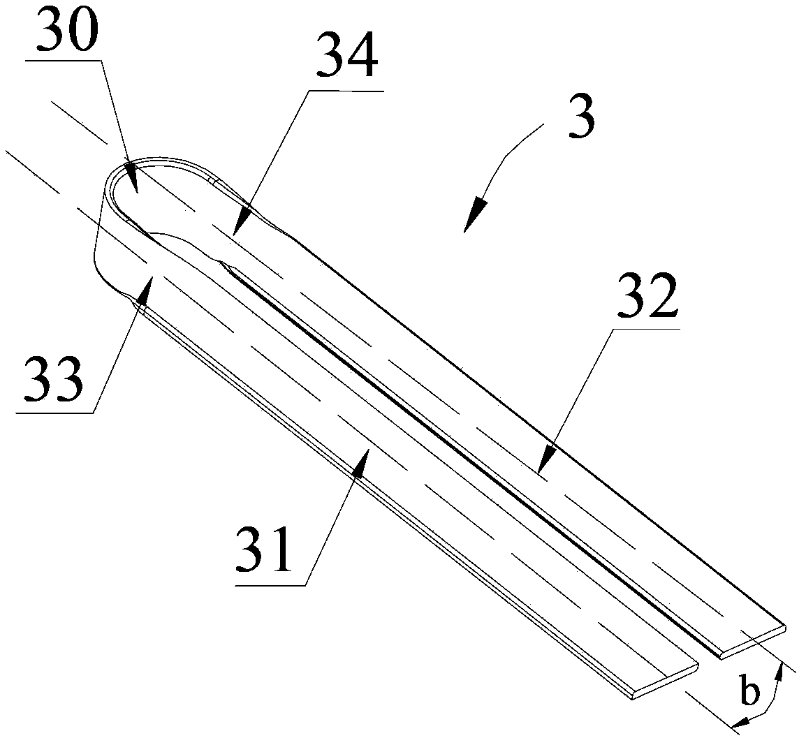
[0030] Please refer to figure 1 and figure 2 As shown, the present invention discloses a heat exchanger 100, which includes a first header 1, a second header 2, and a connection between the first header 1 and the second header 2. Several flat tubes 3 between them, and several fins 4 between adjacent flat tubes 3 . In the illustrated embodiment of the present invention, the heat exchanger 100 is a microchannel heat exchanger.

[0031] The first header 1 and the second header 2 are arranged parallel to each other and spaced apart on both sides of the heat exchanger 100 , one of which is an inlet pipe and the other is an outlet pipe. In the illustrated embodiment of the present invention, in order to improve the compressive strength of the entire heat exchanger 100, the first and second headers 1 and 2 are both cylindrical. The first and second headers 1 and 2 both extend vertically. Of course, in other embodiments, the positional relationship between the first and second he...


PUM


Abstract

Provided are a heat exchanger (100) and a machining method for the heat exchanger. The heat exchanger (100) comprises a first header pipe (1), a second header pipe (2), several flat pipes (3) and several fins (4). The flat pipe (3) comprises an intermediate part (30), a first straight part (31) twisted relative to the intermediate part (30), a second straight part (32) twisted relative to the intermediate part (30), a first twist part (33) connecting the intermediate part (30) and the first straight part (31), and a second twist part (34) connecting the intermediate part (30) and the second straight part (32). The first straight part (31) and the second straight part (32) are respectively positioned at the two sides of the intermediate part (30) and roughly positioned in the same plane. Fins (4) are welded between adjacent first straight parts (31), and fins (4) are welded between adjacent second flat and straight parts (32).

Description

technical field [0001] The invention relates to a heat exchanger and a processing method thereof, belonging to the field of microchannel heat exchangers. Background technique [0002] CN 301439466 S design patent published on January 12, 2011 discloses a bent heat exchanger, which includes two headers, several flat tubes and fins, wherein the flat tubes are After being twisted and bent, a bent heat exchanger with a smaller volume is obtained. However, from the drawing of the appearance design, the middle part will protrude from the heat exchanger after being bent, and the bending size is difficult to control. More importantly, in the actual processing process, if the twisting and bending of the flat tube are placed in the last process, the fins that have been installed before will often be strained during twisting and bending, resulting in heat transfer. Defective device. [0003] Therefore, how to improve the processing technology of the heat exchanger has become a techn...

Claims


Application Information

Patent Timeline
IPC IPC(8): F28D1/053B23P15/26
CPCF28D1/047F28F1/126F28D1/0476F28F2255/00
Inventor 不公告发明人
Owner SANHUA HANGZHOU MICRO CHANNEL HEAT EXCHANGER
Why Eureka
Try Eureka