
A hole checking device

A technology of inspection devices and camera devices, applied in measuring devices, instruments, scientific instruments, etc.

Active Publication Date: 2015-02-11
KK TOSHIBA
View PDF7 Cites 4 Cited by
  • Summary
  • Abstract
  • Description
  • Claims
  • Application Information

AI Technical Summary

Problems solved by technology

[0006] However, in such a hole inspection device, the CCD and CMOS imaging elements are affected by cosmic ray particles (α-rays, neutron rays, etc.), and the output signal (video signal) is random Spike white noise (white noise) is generated, and sometimes the white noise is mistakenly detected as a hole detection signal

Method used


Image

  • A hole checking device
  • A hole checking device
  • A hole checking device

Examples


Embodiment Construction

[0037] Next, a hole inspection device according to an embodiment will be described with reference to the drawings.

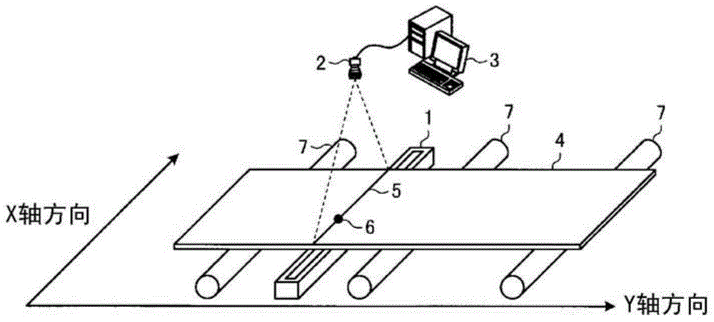
[0038] The hole inspection device of this embodiment removes white noise caused by cosmic ray particles generated on the output signal (video signal) of a CCD camera or a CMOS camera (hereinafter referred to as a camera) through image processing, thereby preventing erroneous detection of holes . figure 1 The overall structure including the hole inspection device of this embodiment and the steel plate to be inspected is shown. In addition, the inspection object is not limited to the steel plate, and any plate-shaped object can be used as the inspection object of the hole inspection device of this embodiment.

[0039] The hole inspection device includes a lighting device 1 (hereinafter referred to as lighting 1 ), such as an LED or a fluorescent lamp, a camera 2 , and a PC 3 for performing image processing. At the inspection site, such as figure 1 As shown, in ...


PUM


Abstract

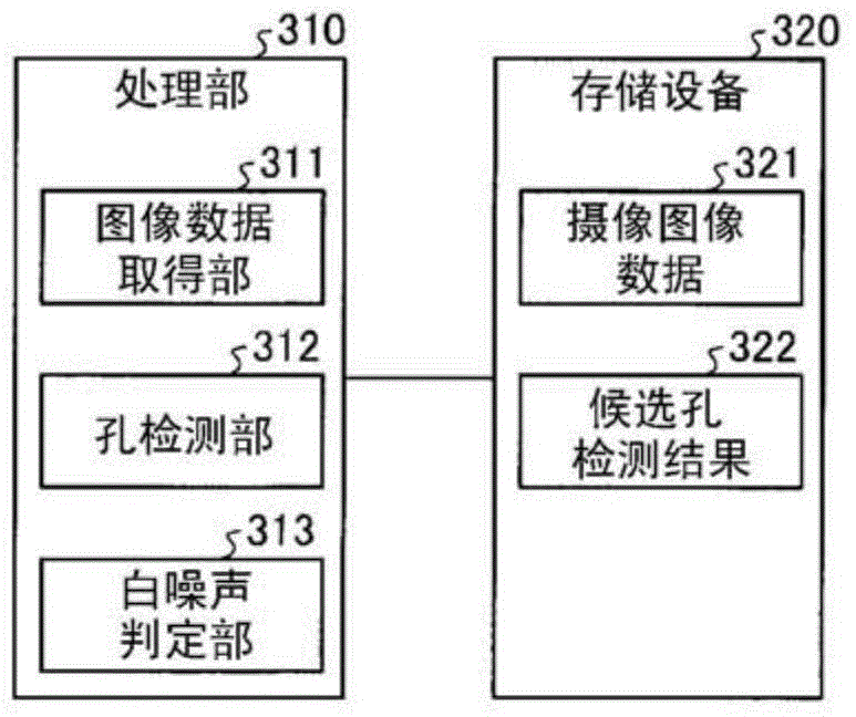
The invention provides a hole checking device capable of preventing error detection of holes caused by cosmic-ray mesons. The hole checking device in an embodiment is provided with an image data acquiring part, a hole detection part and a white noise determining part. The image data acquiring part acquires camera image data of an object to be checked. The hole detection part detects zones having luminance exceeding the candidate hole detection threshold in zones having a specified and determined size corresponding to the size of the hole to be detected, from a line of the camera image data having a specified width determined corresponding to the size of the hole to be detected in a direction orthometric to a conveying direction of the object to be detected, and adopts the zones as candidate holes. The white noise determining part determines that the candidate holes detected by the hole detection part as white noise, under the circumstance that the hole detection part detects candidate holes in a certain line of the camera image data, and does not detect candidate holes in a line of the camera image date next to the certain line of the camera image data.

Description

technical field [0001] Embodiments of the present invention relate to a hole inspection device. Background technique [0002] In the past, in order to detect the hole produced in the steel plate, the following method has been widely used, that is, in the state where the steel plate to be inspected is placed between the illuminating lamp and the camera, the illumination light passing through the through hole of the steel plate is photographed by the imaging device, according to Images are taken to detect holes. [0003] prior art literature [0004] patent documents [0005] Patent Document 1: Japanese Patent Laid-Open No. 2001-249005 [0006] However, in such a hole inspection device, the CCD and CMOS imaging elements are affected by cosmic ray particles (α-rays, neutron rays, etc.), and the output signal (video signal) is random Spike white noise (white noise) is generated frequently, and the white noise is sometimes misdetected as a hole detection signal. Contents of...

Claims


Application Information

Patent Timeline
Patent Type & Authority Applications(China)
IPC IPC(8): G01N21/894
CPCG01N21/894
Inventor 中尾努
Owner KK TOSHIBA
Learn More