
Master cylinder

A technology of active cylinder and clutch, applied in the direction of fluid drive clutch, non-mechanical drive clutch, fluid pressure actuating device, etc., can solve problems such as system damage

Inactive Publication Date: 2015-02-11
SCHAEFFLER TECH AG & CO KG
View PDF5 Cites 6 Cited by
  • Summary
  • Abstract
  • Description
  • Claims
  • Application Information

AI Technical Summary

Problems solved by technology

Depending on the operating state, it is possible, in particular in the event of improper use, that very high pressures can arise in the system which can lead to damage to the system

Method used


Image

  • Master cylinder
  • Master cylinder
  • Master cylinder

Examples


Embodiment Construction

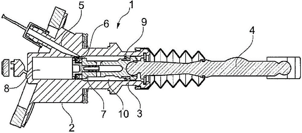
[0023] figure 1 A master cylinder 1 in the prior art is shown. The master cylinder 1 has a master cylinder housing 2 in which a piston 3 is guided so as to be axially displaceable. The piston 3 is pressed in axial direction via a piston rod 4 into the cylinder interior, for example by a pedal (not shown). The flow pipe 5 is connected with a flow container (not shown). The piston has a piston seal 6 which is fastened to the piston by means of a piston insert 7 and delimits a pressure chamber 8 in the cylinder. The secondary piston seal 9 delimits a follower chamber 10 . A pressure line (not shown) leads from the pressure chamber 8 to a slave cylinder (not shown).

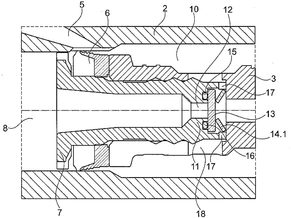
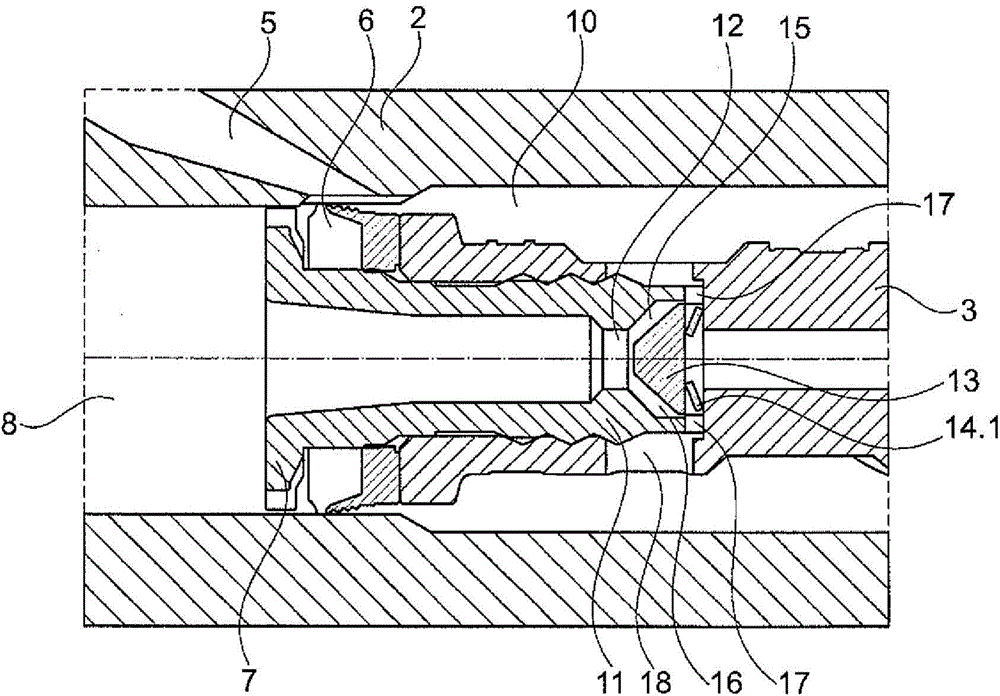
[0024] figure 2 shows a part of the master cylinder 1 according to the invention, which is in principle compatible with figure 1 Active cylinders in the prior art are constructed similarly. In this embodiment, the piston insert 7 extends to an overload valve 11 . The overload valve 11 has a bore 12 which ext...


PUM


Abstract

The present invention relates to a master cylinder for a hydraulic system, in particular a clutch release system, having a housing which has a connector for a follow-up line, a piston with a piston seal, which piston is mounted axially displaceably in the housing and delimits a pressure chamber, and a second seal which is arranged in the housing or on the piston, on the side which faces away from the pressure chamber, and delimits a follow-up chamber, characterized in that an overload valve is arranged in the master cylinder, which overload valve opens a fluid connection between the pressure chamber and the follow-up chamber if a predefined pressure is exceeded.

Description

technical field [0001] The invention relates to a master cylinder for use in a hydraulic system, in particular a clutch release system, having the features of the preamble of claim 1 . Background technique [0002] Master cylinders for hydraulic systems are known in various embodiments from the prior art. Usually, such master cylinders have: a housing with a connection for the follower line; and a second seal delimiting the follower chamber. On the piston there are connections for the lines of the hydraulic system in which hydraulic pressure can be generated by means of the active piston. Since the active cylinder is usually operated by operating the pedal, the maximum pressure that occurs in this system is directly proportional to the maximum force that the user can exert on the operating pedal. This maximum force is related on the one hand to the actually existing force that the user can exert purely physically on the actuating pedal and on the other hand to the reactio...

Claims


Application Information

Patent Timeline
Patent Type & Authority Applications(China)
IPC IPC(8): F15B7/08F16D25/08F16D48/02
CPCF16D2025/081F16D25/08F15B7/08F15B15/204F16D2048/0263F16D2048/0212
Inventor S·奥特曼P·瓦格纳J·奥斯特
Owner SCHAEFFLER TECH AG & CO KG
Features
  • Generate Ideas
  • Intellectual Property
  • Life Sciences
  • Materials
  • Tech Scout
  • Unparalleled Data Quality
  • Higher Quality Content
  • 60% Fewer Hallucinations
Learn More