Vibration type driving apparatus, two-dimensional driving apparatus, image-blur correction apparatus, interchangeable lens, image-pickup apparatus, and automatic stage
A technology for driving equipment and image pickup components, applied in image communication, microscopes, generators/motors, etc., can solve the problems of output loss, energy loss, characteristic degradation, etc., and achieve the effect of solving the output loss problem
- Summary
- Abstract
- Description
- Claims
- Application Information
AI Technical Summary
Problems solved by technology
Method used
Image
Examples
no. 1 example
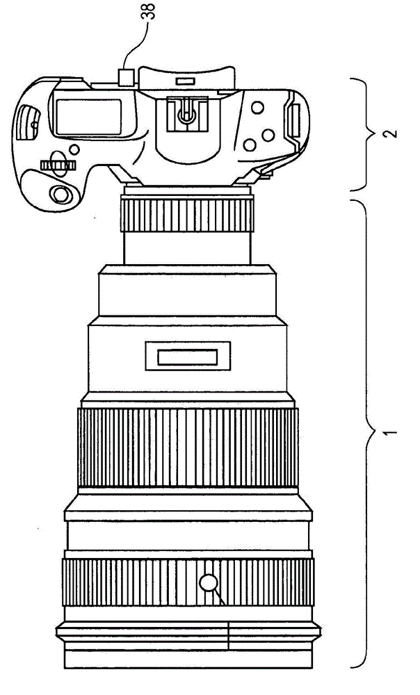
[0070] figure 1 is a schematic diagram of a camera as an image pickup device according to a first embodiment of the present invention. figure 1 The camera in has the function of capturing moving images and still images. Reference numeral 1 denotes a lens barrel equipped with an image blur correction device, and reference numeral 2 denotes a camera body including an image pickup element 36 (photoelectric conversion element, etc.).
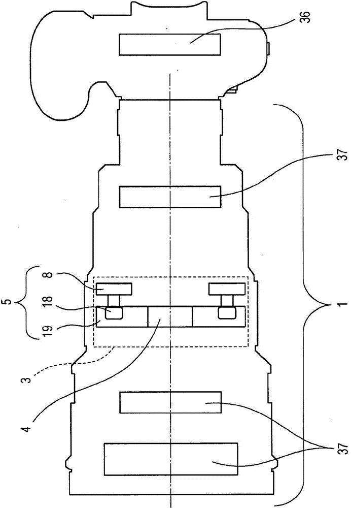
[0071] figure 2 is a schematic diagram of the interior of the lens barrel 1 and the camera body 2 . Reference numeral 3 designates an image blur correction device. Reference numeral 4 designates an optical lens. Reference numeral 5 designates a vibration-type drive device; 19 designates a movable body to which the optical lens 4 is mounted; and 18 designates a driven body driven by a vibrator 8 . The driven body 18 has a configuration for transmitting displacement and force to the movable body 19 . In this configuration, the vibrator 8 can mo...
no. 2 example
[0099] Figure 11 is a perspective view of a microscope as an image pickup device according to a second embodiment of the present invention. Figure 11 The microscope in includes: an image pickup section 30 housing an image pickup element and an optical system; and an automated stage 31 having a two-dimensional drive device 32 . An observation target is placed on the two-dimensional drive device 32 , and an enlarged image is obtained by the optical pickup section 30 . In the case of a wide observation range, the observation target is made to move along the Figure 11 The X direction and Y direction movement in order to obtain a large number of images. A computer (not shown) can combine the acquired images to obtain high resolution images over a wide viewing field.
[0100] Here, the two-dimensional drive device 32 will be described. Figure 12 is a perspective view of the two-dimensional drive device 32 . The functional difference between the two-dimensional driving devic...
no. 3 example
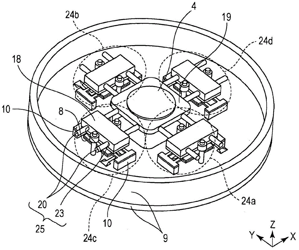
[0103] The third embodiment differs from the first embodiment in the configuration of the movement mechanism 25 . This will be described. Figure 13A is a perspective view of the kinematic mechanism 25 and the driven body 18 . Figure 13B is its front view. The X direction in the figure is the driving direction (first direction) of the vibration type driving device 24 . The Y direction is a yaw direction (second direction) along which the movable body 19 and the driven body 18 can move relative to each other by means of the movement mechanism 25 .
[0104]The guide members 20 are connected to the movable body 19 and have a trapezoidal shape in cross-section in the X and Y directions and each have a groove in the Y direction (the deflection direction or the second direction). The follower transmission portions 23 of the follower 18 have a trapezoidal shape in cross-section in the X and Y directions and each have a groove extending in the Y direction (the deflection direction...
PUM
 Abstract
Description
Claims
Application Information
 - R&D
- Intellectual Property
- Life Sciences
- Materials
- Tech Scout
- Unparalleled Data Quality
- Higher Quality Content
- 60% Fewer Hallucinations
Browse by: Latest US Patents, China's latest patents, Technical Efficacy Thesaurus, Application Domain, Technology Topic, Popular Technical Reports.
© 2025 PatSnap. All rights reserved.Legal|Privacy policy|Modern Slavery Act Transparency Statement|Sitemap|About US| Contact US: help@patsnap.com


