Electrohydraulic automatic clutch actuating mechanism

An automatic clutch and actuator technology, applied in non-mechanical drive clutches, clutches, mechanical equipment, etc., can solve the problems of large motor drive power loss, uncompact structure, large volume, etc. Small size effect

Inactive Publication Date: 2019-04-23
UNITED AUTOMOTIVE ELECTRONICS SYST
View PDF5 Cites 0 Cited by
  • Summary
  • Abstract
  • Description
  • Claims
  • Application Information

AI Technical Summary

Problems solved by technology

[0006] The object of the present invention is to provide an electro-hydraulic automatic clutch actuator to solve the problems of uncompact structure, large volume and large power loss of motor transmission in the prior art.

Method used


Image

  • Electrohydraulic automatic clutch actuating mechanism
  • Electrohydraulic automatic clutch actuating mechanism
  • Electrohydraulic automatic clutch actuating mechanism

Examples


Embodiment Construction

[0025] An electro-hydraulic automatic clutch actuator proposed by the present invention will be described in further detail below in conjunction with the accompanying drawings and specific embodiments. Advantages and features of the present invention will be apparent from the following description and claims. It should be noted that all the drawings are in a very simplified form and use imprecise scales, and are only used to facilitate and clearly assist the purpose of illustrating the embodiments of the present invention.

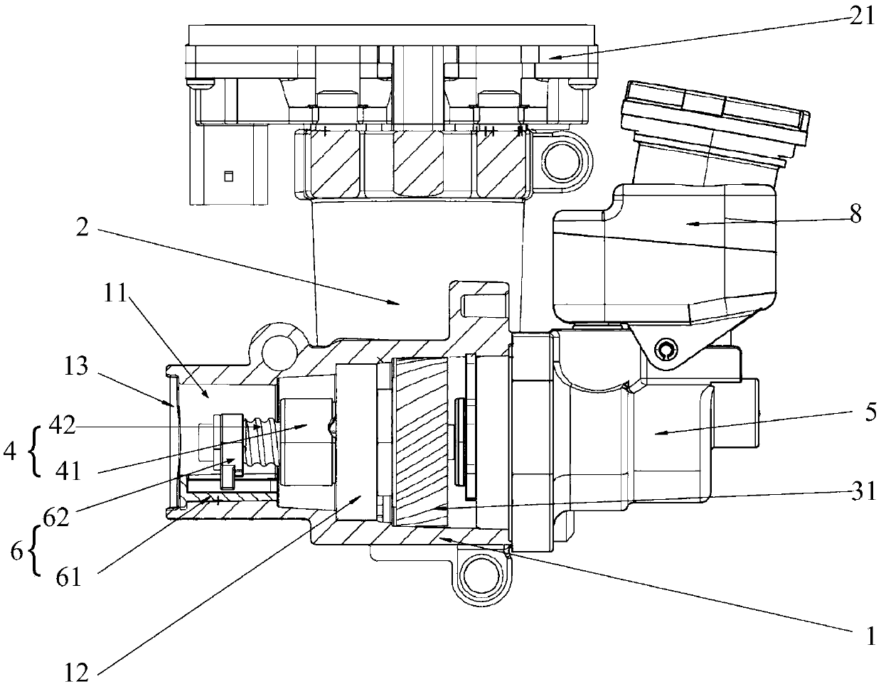
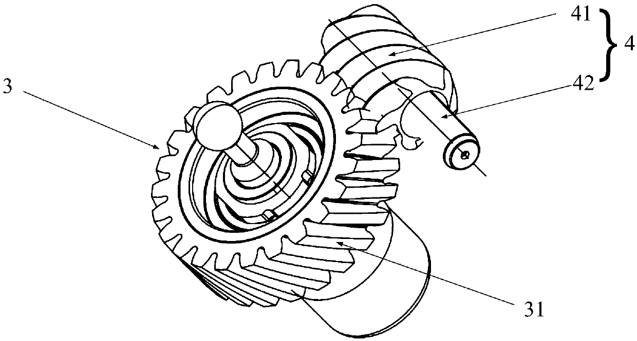
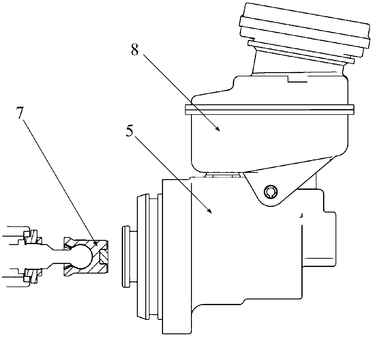
[0026] figure 1 It is a schematic diagram of an electro-hydraulic automatic clutch actuator provided by an embodiment of the present invention. Please refer to figure 1 , an electro-hydraulic automatic clutch actuator, including a housing 1, a motor 2, a worm gear 3, a ball screw 4, and a hydraulic master cylinder 5; the housing 1 has an inner cavity 11 penetrating along a first direction, so One end of the inner chamber 11 is sealed by a plug cover 13,...


PUM


Abstract

The invention provides an electrohydraulic automatic clutch actuating mechanism which comprises a motor, a worm gear, a ball screw, a housing and a main hydraulic cylinder, wherein the housing is provided with an inner cavity penetrating in an extension direction of the housing; one end of the inner cavity is sealed by a plug lid; the other end of the inner cavity is in sealing connection with themain hydraulic cylinder; a bearing is fixedly arranged in the inner cavity; the ball screw is arranged in the inner cavity; a nut of the ball screw is rotationally connected with the bearing; one end, close to the plug lid, of a threaded rod of the ball screw is free; the other end of the threaded rod extends into the main hydraulic cylinder and is connected with a piston of the main hydraulic cylinder; the motor is in sealing connection with the housing; an output shaft of the motor penetrates through the housing and is located in the inner cavity; the output shaft of the motor is sleeved with the worm gear; the worm gear is located in the inner cavity; a helical gear of the worm gear is rotationally connected with the nut of the ball screw; and the worm gear rotates to drive the nut torotate. The electrohydraulic automatic clutch actuating mechanism solves the problems that a hydraulic automatic clutch is not compact in structure and large in size, and the loss of power transmittedby the motor is large in the prior art.

Description

technical field [0001] The invention belongs to the field of motor vehicle control and relates to an electro-hydraulic automatic clutch actuator. Background technique [0002] The clutch operating mechanism is a set of mechanisms used by the driver to disengage the clutch and then make it softly engaged. It starts at the clutch pedal and ends at the release bearing inside the flywheel housing. At present, the clutches used in automobiles are divided into traditional clutches and automatic clutches according to the difference between manual transmission and automatic transmission. The difference between the two is mainly reflected in the difference in the clutch control mechanism. [0003] The operating mechanism of the traditional clutch mainly includes a mechanical hydraulic clutch operating mechanism. This operating mechanism is mainly composed of a clutch pedal, a clutch master cylinder, a clutch slave cylinder, etc., and the clutch master cylinder is pushed by the drive...

Claims


Application Information

Patent Timeline
Patent Type & Authority Applications(China)
IPC IPC(8): F16D29/00
CPCF16D29/005
Inventor 李帅汪植亮于明涛朱晨晓王俊淞徐佳惟宋玮峰尹彥斌
Owner UNITED AUTOMOTIVE ELECTRONICS SYST
Why Eureka
Try Eureka