Impeller for fuel pump

a fuel pump and pump body technology, applied in the direction of liquid fuel engines, liquid fuel feeders, machines/engines, etc., can solve the problems of fuel and water swelling, and achieve the effect of reducing the output loss of the fuel pump, reducing power consumption, and reducing the swelling amoun

Inactive Publication Date: 2018-10-18
DENSO CORP +1
View PDF4 Cites 1 Cited by
  • Summary
  • Abstract
  • Description
  • Claims
  • Application Information

AI Technical Summary

Benefits of technology

[0008]However, in view of reducing the output loss of the fuel pump and reducing the power consumption, it is required to find another resin material, which reduces the swelling amount due to the fuel and the water as compared to the PPS resin, to decrease the dimension of the clearance defined between the impeller and the housing.
[0012]Thus, the present disclosure can provide an impeller for a fuel pump of which swelling amount due to the fuel and water is smaller than the swelling amount of the impeller molded by PPS resin.

Problems solved by technology

The swelling amount due to the fuel and the water also may increase when an interface adhesion between resin and the glass fiber is weak.

Method used


Image

  • Impeller for fuel pump
  • Impeller for fuel pump
  • Impeller for fuel pump

Examples


Embodiment Construction

[0018]An embodiment of the present disclosure will be described hereafter referring to drawings.

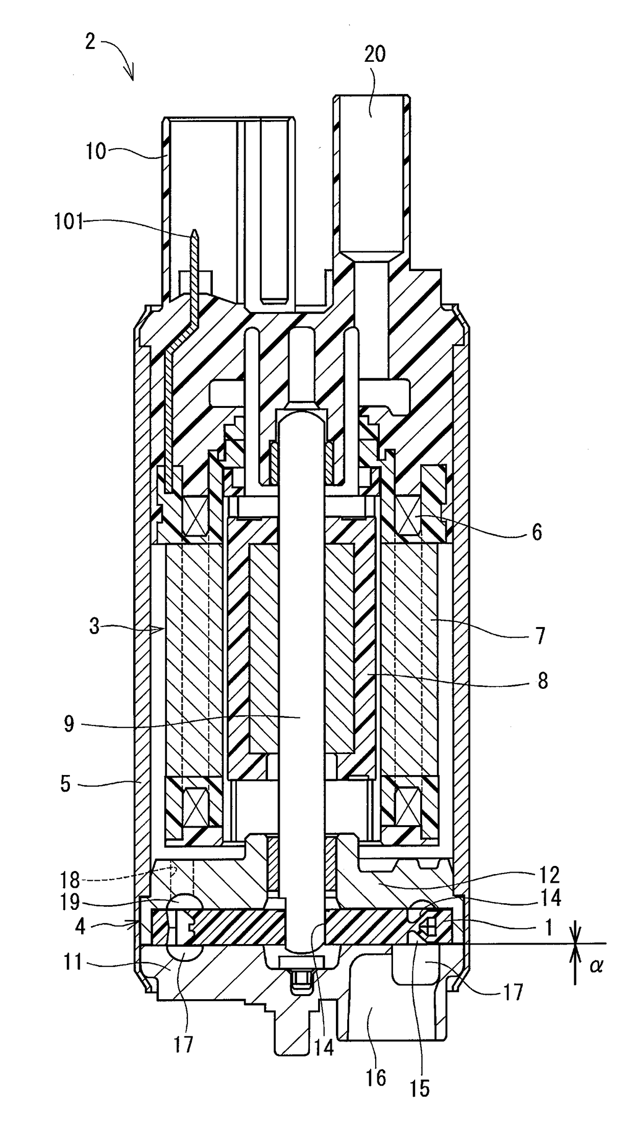
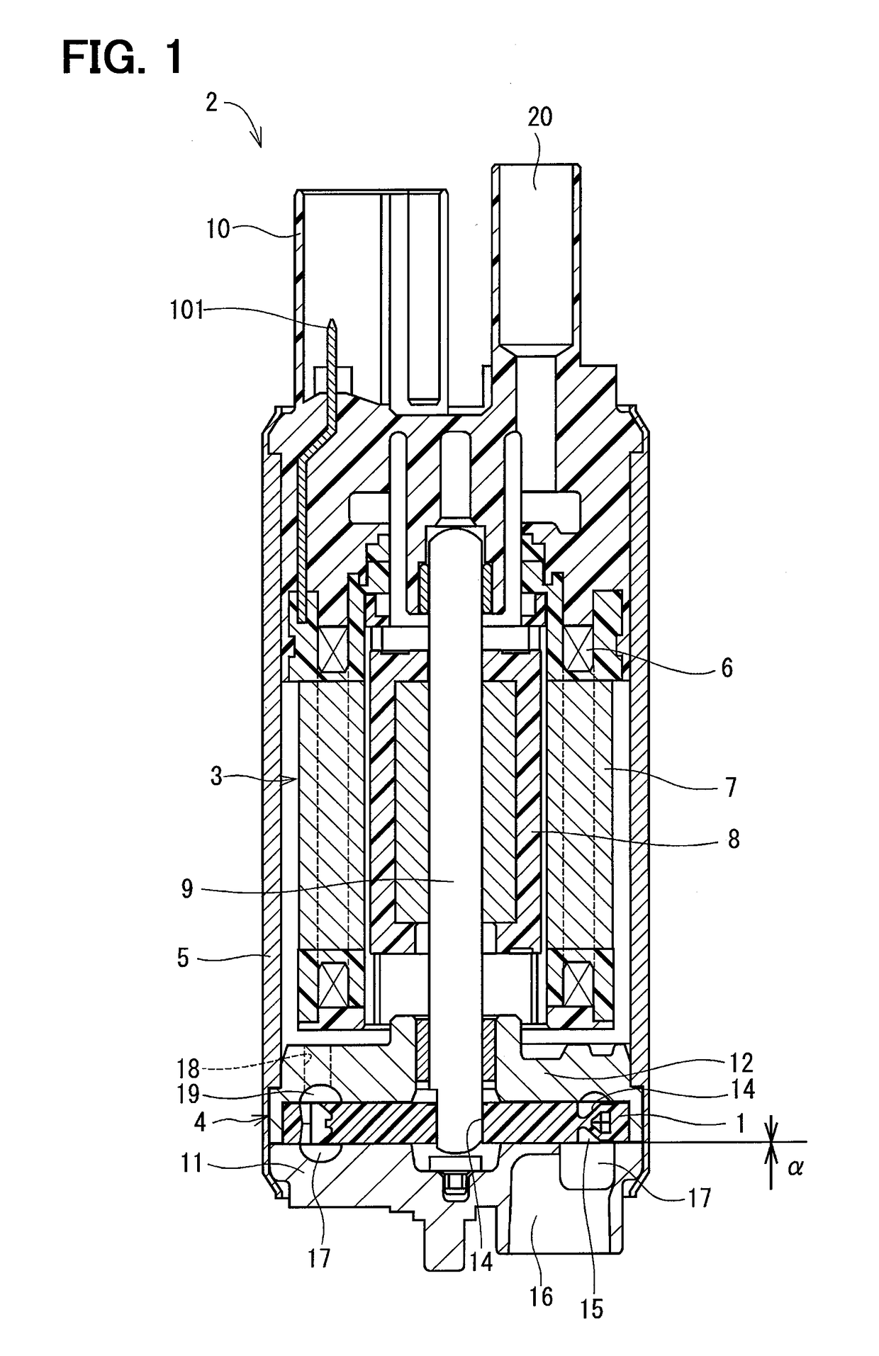
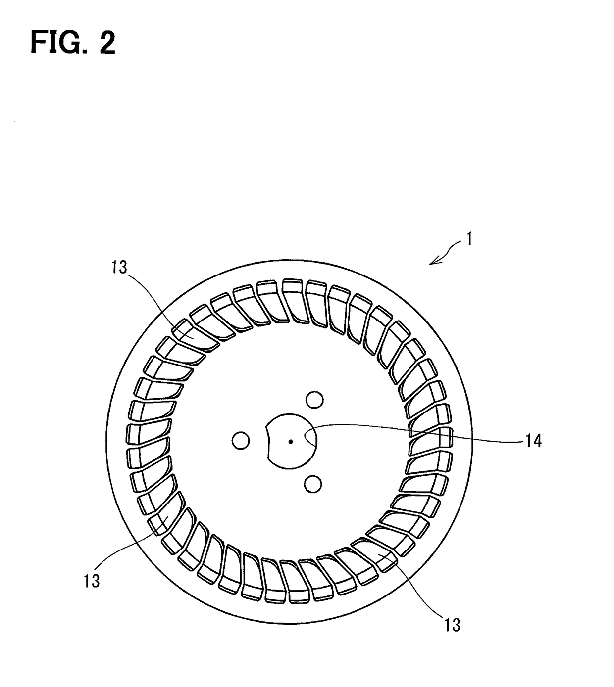
[0019]FIG. 1 shows a fuel pump 2 mounting an impeller 1 in the embodiment of the present disclosure.

[0020](Configuration of Fuel Pump)

[0021]A configuration of the fuel pump 2 will be described hereafter. The fuel pump 2 includes a motor 3 and a pump 4. The motor 3 and the pump 4 are assembled integrally with each other by a pump case 5 having a tubular shape.

[0022]The motor 3 includes a stator 7, a rotor 8, and a shaft 9. A coil 6 is wound around the stator 7. The rotor 8 is rotatably positioned inside the stator 7. The shaft 9 rotates together with the rotor 8. The stator 7 generates a rotational magnetic field when electric power is applied to the coil 6, wound around the stator 7, from a terminal 101 of a connector 10. The rotor 8, in which an N pole and an S pole are alternately magnetized in a circumferential direction, rotates together with the shaft 9 around a rotational axis.

[0023...


PUM

PropertyMeasurementUnit
spin-spin relaxation timeaaaaaaaaaa
mass %aaaaaaaaaa
mass %aaaaaaaaaa

Abstract

An impeller for a fuel pump is molded by a molding material containing a phenolic resin and an inorganic filler. A content at a minimum spin-spin relaxation time is 70% or higher with respect to a whole when approximating a free induction decay curve, which is obtained by Solid Echo Method in a pulse NMR measurement at 90° C., with a sum of relaxation curves of three components. The content at the minimum spin-spin relaxation time corresponds to a content of a portion of the phenolic resin, which forms the impeller for the fuel pump, where a cross-linking reaction is caused. A swelling amount of the impeller due to a liquid containing a fuel and water decreases as a crosslink density of the phenolic resin increases. The swelling amount of the impeller in the present disclosure is smaller than the swelling amount of an impeller molded by PPS resin.

Description

CROSS REFERENCE TO RELATED APPLICATION[0001]This application is based on and claims the benefit of priority from Japanese Patent Application No. 2015-212692 filed on Oct. 29, 2015. The entire disclosure of the application is incorporated herein by reference.TECHNICAL FIELD[0002]The present disclosure relates to an impeller for a fuel pump.BACKGROUND ART[0003]A fuel pump mounted to a vehicle or the like includes a housing and an impeller. The housing includes an inner wall defining a pump chamber into which a fuel flows. The impeller is made of resin and housed in the housing. The impeller is positioned such that a clearance having a specified dimension is secured between the inner wall and the impeller. The impeller may be swelled due to the fuel and water contained in the fuel, therefore a rotation of the impeller may be stopped when the impeller is swelled and comes in contact with the housing. Thus, the dimension of the clearance is set to prevent the impeller from coming in cont...

Claims


Application Information

Patent Timeline
Patent Type & Authority Applications(United States)
IPC IPC(8): F02M37/10C08L61/06C08K5/3477C08K7/14C08K3/36C08K3/34
CPCF02M37/10C08L61/06C08K5/3477C08K7/14C08K3/36C08K3/346C08K3/34F04D5/00F04D29/02
Inventor OKUYA, TAKAHIROHIDAKA, YUUJIKOIZUMI, KOJIWATANABE, YUSUKEIGAWA, RYOICHI
Owner DENSO CORP
Why Eureka
Try Eureka