Solar cell module and method of fabricating the same

a solar cell module and solar cell technology, applied in the field of solar cell modules, can solve the problems of power loss in the range of about 5% to about 10%, and achieve the effects of reducing the non-active area, improving the photoelectric output of the solar cell module according to the embodiment, and reducing the output power loss of the solar cell modul

Inactive Publication Date: 2016-06-28
LG INNOTEK CO LTD
View PDF18 Cites 0 Cited by
  • Summary
  • Abstract
  • Description
  • Claims
  • Application Information

AI Technical Summary

Benefits of technology

[0011]The solar cell module according to the embodiment has a structure in which the solar cells are repeatedly disposed in the longitudinal direction. The structure may allow the non-active area to be minimized, so that the loss of the output power of the solar cell module may be reduced from the range of 5% to 10% to the range of 0.5% to 2.0%. Thus, the photoelectric output of the solar cell module according to the embodiment may be improved.
[0012]In addition, since the solar cell module has a structure in which an electron-transfer path may be minimized, the series resistance is reduced and the short current is increased, so that the photoelectric output is increased.

Problems solved by technology

The non-active area (NAA) leads to a power loss in the range of about 5% to about 10% based on the whole output power of the solar cell module.

Method used


Image

  • Solar cell module and method of fabricating the same
  • Solar cell module and method of fabricating the same
  • Solar cell module and method of fabricating the same

Examples


Embodiment Construction

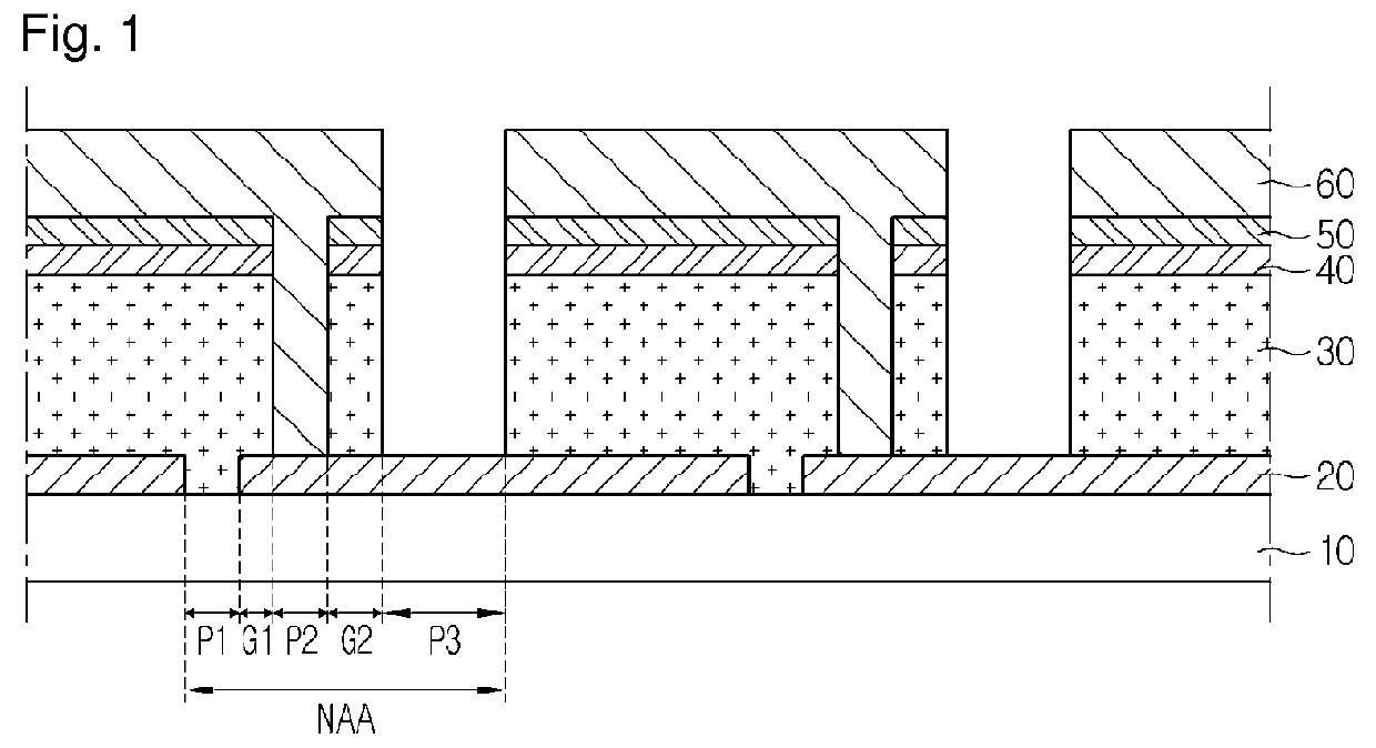
[0017]In the description of the embodiments, it will be understood that, when a substrate, a layer, a film, or an electrode is referred to as being “on” or “under” another substrate, another layer, another film, or another electrode, it can be “directly” or “indirectly” on the other substrate, the other layer, the other film, or the other electrode, or one or more intervening layers may also be present. Such a position of each component has been described with reference to the drawings. The thickness and size of each component shown in the drawings may be exaggerated, omitted or schematically drawn for the purpose of convenience or clarity. In addition, the size of elements does not utterly reflect an actual size.

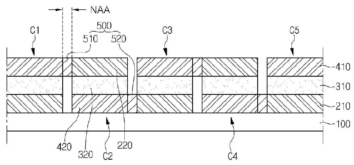
[0018]FIG. 2 is a sectional view showing the solar cell module according to the embodiment. Referring to FIG. 2, the solar cell module according to the embodiment includes first solar cells C1, C3 and C5, second solar cells C2 and C4, and a connecting electrode 500 which co...


PUM


Abstract

Disclosed are a solar cell module and a method of fabricating the same. The solar cell module according to the embodiment includes first solar cells including a first P-type semiconductor layer, a first buffer layer, and a first N-type semiconductor layer sequentially disposed on a support substrate; second solar cells including a second N-type semiconductor layer, a second buffer layer, and a second N-type semiconductor layer sequentially disposed on the support substrate; and a connecting electrode connecting the first solar cells to the second solar cells.

Description

CROSS-REFERENCE TO RELATED APPLICATIONS[0001]This application is the U.S. national stage application of International Patent Application No. PCT / KR2012 / 010719, filed Dec. 10, 2012, which claims priority to Korean Application No. 10-2011-0132371, filed Dec. 9, 2011, the disclosures of each of which are incorporated herein by reference in their entirety.TECHNICAL FIELD[0002]The embodiment relates to a solar cell module and a method of fabricating the same.BACKGROUND ART[0003]Solar cells may be defined as devices to convert light energy into electrical energy by using photovoltaic effect of generating electrons when light is incident onto a P-N junction diode. The solar cell may be classified into a silicon solar cell, a compound semiconductor solar cell mainly including a group I-III-VI compound or a group III-V compound, a dye-sensitized solar cell, and an organic solar cell according to materials constituting the junction diode.[0004]A solar cell made from CIGS (CuInGaSe), which is ...

Claims


Application Information

Patent Timeline
Patent Type & Authority Patents(United States)
IPC IPC(8): H01L31/05H01L31/02H01L31/0749
CPCH01L31/0504H01L31/02008H01L31/0749Y02E10/541H01L31/06H01L31/18H01L31/0445
Inventor JEE, SUK JAE
Owner LG INNOTEK CO LTD
Why Eureka
Try Eureka