Francis-type hydraulic turbine wheel equipped with a tip-forming member, and method of reducing fluctuations using such a wheel

a technology of hydraulic turbine wheel and tip-forming member, which is applied in the direction of propellers, propulsive elements, water-acting propulsive elements, etc., can solve the problem of not decreasing the output of the turbine to an inconvenient extent, and achieve the effect of not increasing the output loss

Inactive Publication Date: 2014-11-25
ALSTOM RENEWABLE TECH
View PDF22 Cites 0 Cited by
  • Summary
  • Abstract
  • Description
  • Claims
  • Application Information

AI Technical Summary

Benefits of technology

[0009]The present invention is intended more particularly to address these disadvantages by proposing a new Francis-type wheel, with which a turbine or a turbine pump can be equipped, and in which turbulence phenomena at the outlet from the turbine are minimized and the output losses are not increased as a result of the use of this member.

Problems solved by technology

The principal flow of water is not disrupted to a significant extent, however, and the output of the turbine is not decreased to an inconvenient extent.

Method used


Image

  • Francis-type hydraulic turbine wheel equipped with a tip-forming member, and method of reducing fluctuations using such a wheel
  • Francis-type hydraulic turbine wheel equipped with a tip-forming member, and method of reducing fluctuations using such a wheel
  • Francis-type hydraulic turbine wheel equipped with a tip-forming member, and method of reducing fluctuations using such a wheel

Examples


first embodiment

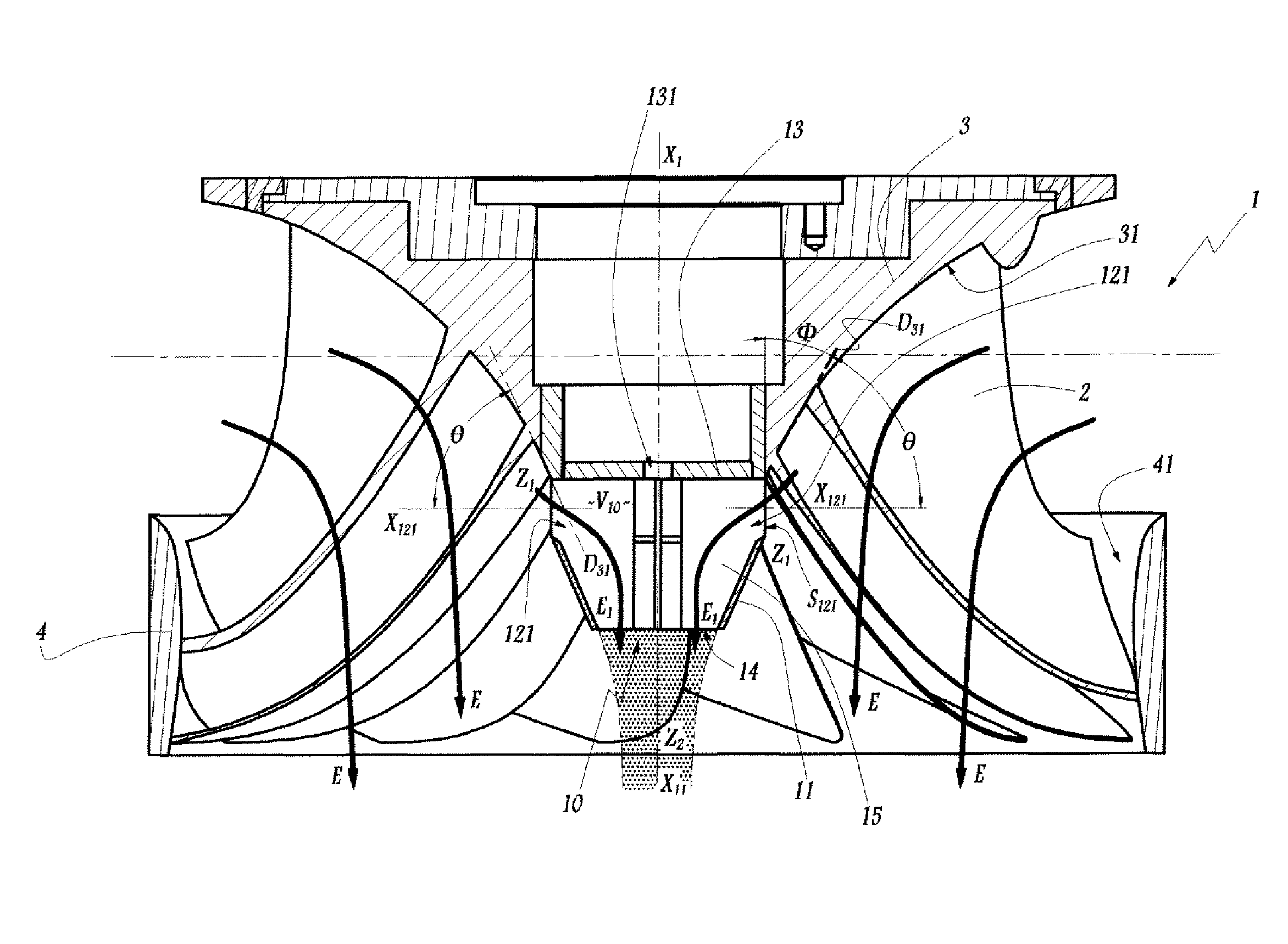
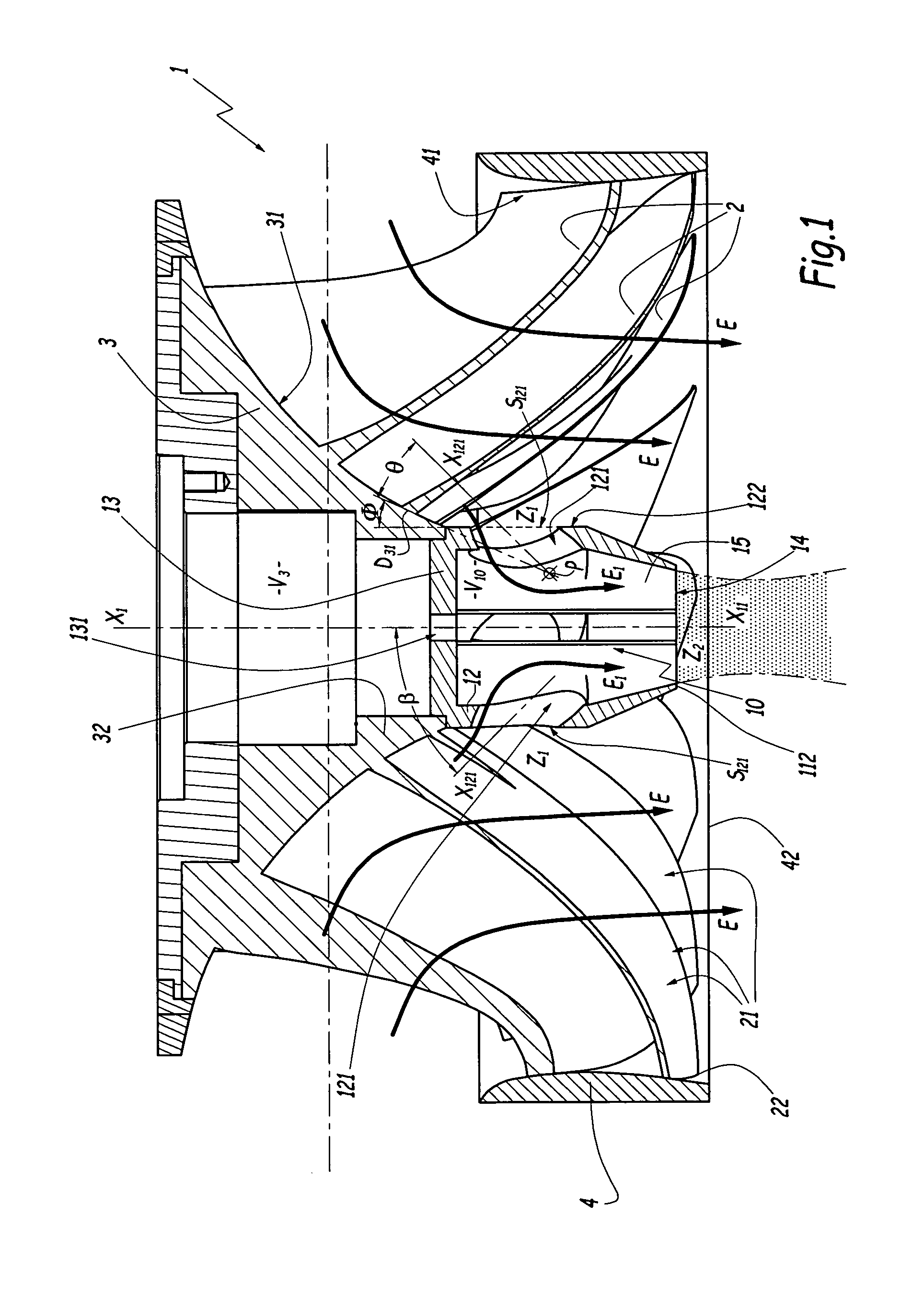
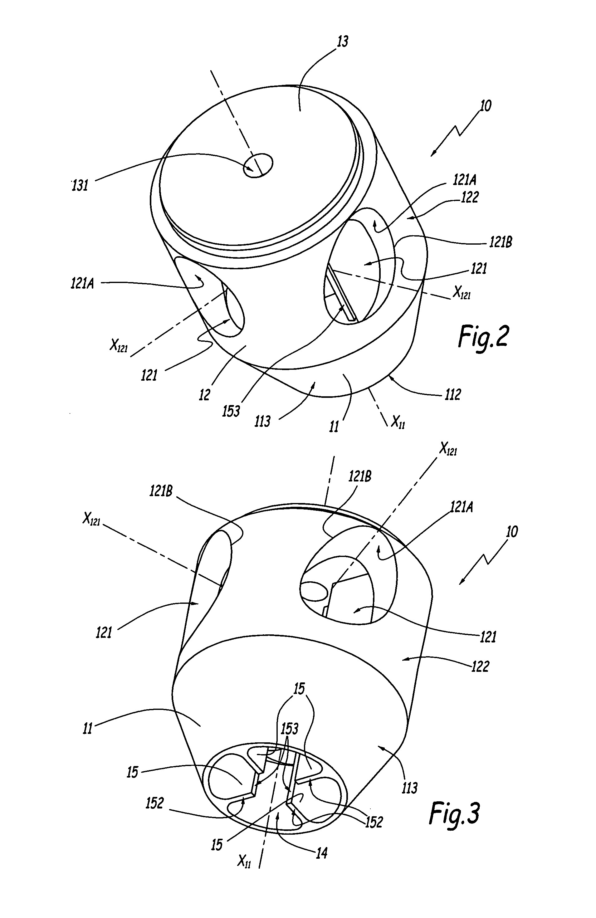
[0070]In the embodiment of the invention depicted in FIGS. 9 to 12, the elements similar to those of the first embodiment bear the same references. A Francis-type turbine wheel 1 comprises vanes 2 arranged between the respective wet surfaces 31 and 41 of a crown 3 and a belt 4. The member 10 in this embodiment also comprises a ceiling 13 pierced by an opening 131 for the passage of a means of fixation on the wheel 1. The member 10 is provided with a frustoconical skirt 11 that is also convergent opposite the ceiling 13. Four fins 15, arranged at 90° around the axis of symmetry X11 of the skirt 11, connect this skirt to the ceiling 13, maintaining a gap between the upper edge 111 of the skirt 11 and the outer radial edge 132 of the ceiling 13, which is in the form of a disk. Formed in this way is an opening 121 which extends for substantially the entire circumference of the member 10, only being interrupted every 90° by an external radial edge 151 of a fin 15, which forms a leading e...

second embodiment

[0085]A member according to the invention can be mounted on a wheel equipping a turbine pump. When used in pump mode, the flow takes place in the opposite direction from that represented by the arrows E and E1 in the figures, and it is important to be able to close off the openings 121 when the wheel is optimal operating condition, as explained with reference to the

[0086]The invention has been represented by members 10 provided with a ceiling 13 for mounting on a wheel 1. A ceiling of this kind is not mandatory and can be replaced by other linking parts on the crown or on the hub of the wheel, for example a flange, whether open or not.

[0087]The invention has been represented by a member 10 bolted to the crown 3 of a wheel. Such a member may be attached to the wheel by different means, for example by welding.

[0088]The invention has been represented by a member 10 intended to be attached to the crown of a wheel 1. It is also applicable in the case where a tip-forming member is an inte...


PUM


Abstract

This wheel comprises a plurality of vanes (2) arranged on a crown (3) and is equipped with a tip-forming member (10) attached to a central region (32) of the crown or hub of the wheel (1), radially inside the vanes (2), the crown defining a wet surface (31) for guiding a flow (E) passing between the vanes. The tip-forming member (10) is provided with at least one opening (121) for diverting a fraction (E1) of the flow towards the internal volume (V10) of this member. This member comprises a frustoconical annular skirt (11) and at least one fin (15) arranged in its internal volume (V10) and able to modify the path of the flow fraction (E1) entering this volume through the opening (121). This fin (15) extends as far as the edge (112) of the skirt (11) which defines an outlet opening (14) of the member (10) for the flow fraction (E1).

Description

BACKGROUND OF THE INVENTION[0001]1. Field of the Invention[0002]The present invention relates to a Francis-type wheel of a hydraulic machine equipped with a tip-forming member which in the main extends the crown of the wheel. The invention also relates to a method of reducing the fluctuations in a flow interacting with such a wheel.[0003]2. Brief Description of the Related Art[0004]Previously disclosed in the field of hydraulic turbines, in particular Francis-type turbines, is the equipment of the downstream region of the crown of a wheel with an axisymmetric member, often referred to as a “tip”, the external surface of which substantially extends the wetted surface of the crown of the wheel having a diameter which may reduce in the downstream direction. This member or “tip” extends the guiding of the flow into proximity with the axis of rotation of the wheel. Similarly previously disclosed is the use of guiding members or tips in turbine pumps and other paddle turbines.[0005]In pre...

Claims


Application Information

Patent Timeline
Patent Type & Authority Patents(United States)
IPC IPC(8): F03B15/02F03B11/04F03B3/12F03B3/02F03B3/10
CPCF05B2250/25F05B2240/242F03B3/125F03B3/103F03B11/04Y02E10/223Y02E10/226F03B3/02Y02E10/20
Inventor MAZZOUJI, FARIDBAZIN, DANIELECOUSTON, MICHELBERAL, CLAUDEBREMOND, JACQUES
Owner ALSTOM RENEWABLE TECH
Why Eureka
Try Eureka