Eureka AIR delivers breakthrough ideas for toughest innovation challenges, trusted by R&D personnel around the world.

Cam Manipulator

A technology of manipulators and cams, applied in the field of manipulators, can solve the problems that restrict the popularization and application of cam manipulators, and cannot be flexibly selected, and achieve the effects of shortening the development cycle, compact structure, and simple structure

Active Publication Date: 2016-04-06
SUZHOU LING AUTOMATION EQUIP
View PDF6 Cites 0 Cited by
  • Summary
  • Abstract
  • Description
  • Claims
  • Application Information

AI Technical Summary

Problems solved by technology

However, in the actual application practice of the manipulator, it has also been found that there are obvious defects in the existing direct-acting and direct-acting cam manipulators, that is, the angle between the axis of the power input shaft and the motion plane of the manipulator cannot be determined by the user. Flexible selection according to specific layout needs
This defect seriously restricts the popularization and application of cam manipulators

Method used


Image

  • Cam Manipulator
  • Cam Manipulator
  • Cam Manipulator

Examples


Embodiment Construction

[0014] The preferred embodiments of the present invention will be described in detail below in conjunction with the accompanying drawings, so that the advantages and features of the present invention can be more easily understood by those skilled in the art, so as to define the protection scope of the present invention more clearly.

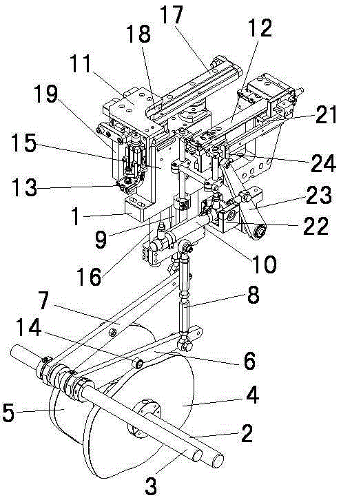
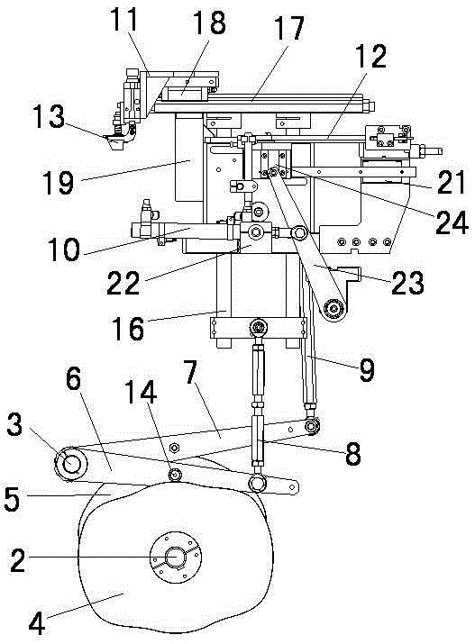
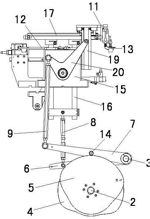
[0015] see Figure 1 to Figure 3 , the embodiment of the present invention includes:

[0016] A cam manipulator, comprising: bracket 1, transmission shaft 2, swing rod fixed shaft 3, lifting cam 4, swing cam 5, lifting swing rod 6, front and rear swing rods 7, lifting pull rod 8, front and rear pull rod 9, feeding cylinder 10 , the manipulator fixed plate 11 and the feeding plate 12; the loading plate 12 has a workpiece placement groove for placing workpieces; Grab the workpiece on the plate 12 and install the workpiece in place; the lifting cam 4 and the swing cam 5 are arranged on the transmission shaft 2, and the transmission shaft 2 drives t...


PUM


Abstract

The invention discloses a cam manipulator which comprises a support, a transmission shaft, a swing rod fixing shaft, a disk cam, a swing rod, a pull rod, a feeding cylinder, a manipulator fixing plate and a feeding plate, wherein the disk cam is arranged on the transmission shaft, and the transmission shaft drives the disk cam; one end of the swing rod is rotatably arranged on the swing rod fixing shaft, and the other end of the swing rod is connected with the pull rod; the pull rod is connected with the manipulator fixing plate; an actuating mechanism is fixedly arranged on the manipulator fixing plate; a cam follower is fixed at the intermediate segment of the swing rod and closely contacts with the disk cam; the disk cam controls the lifting and back-and-forth swing of the manipulator fixing plate through the swing rod and the pull rod; the feeding cylinder is fixed on the support and drives the feeding plate to move back and forth. By the way, the cam manipulator can flexibly select the direction of a power input shaft and is compact in structure and convenient in layout and positioning.

Description

technical field [0001] The invention relates to the field of manipulators, in particular to a cam manipulator. Background technique [0002] The motor-driven manipulator is easy to install, has high flexibility, and can dock at multiple points. If the assembly system needs to be changed or redesigned, simply reprogram it. However, motor-driven manipulators need to be equipped with complex electrical control systems. If such manipulators are used to complete relatively simple repetitive tasks, the cost will be too high. [0003] The cam-type manipulator with the cam as the driving mechanism has the advantages of simple structure, stable movement, accurate phase, fast working rhythm, low failure rate, low cost and long service life. However, in the actual application practice of the manipulator, it has also been found that there are obvious defects in the existing direct-acting and direct-acting cam manipulators, that is, the angle between the axis of the power input shaft an...

Claims


Application Information

Patent Timeline
Patent Type & Authority Patents(China)
IPC IPC(8): B25J9/00B25J9/10
Inventor 王红红
Owner SUZHOU LING AUTOMATION EQUIP
Why Eureka
Eureka Blog
Learn More