Supercharge Your Innovation With Domain-Expert AI Agents!

Novel pressure transmitting mechanism

A transmission mechanism and pressure technology, applied in the direction of conveyor objects, conveyor control devices, transportation and packaging, etc., can solve the problems of easy failure and inconvenient installation of pressure transmission mechanism, so as to reduce failure, facilitate maintenance and improve work efficiency Effect

Inactive Publication Date: 2015-02-18
ZHEJIANG ZHONGJI PILE IND
View PDF5 Cites 1 Cited by
  • Summary
  • Abstract
  • Description
  • Claims
  • Application Information

AI Technical Summary

Problems solved by technology

The commonly used pressure transmission mechanism is inconvenient to install and prone to failure. It is necessary to improve its structure to overcome the above defects

Method used


Image

  • Novel pressure transmitting mechanism

Examples


Embodiment Construction

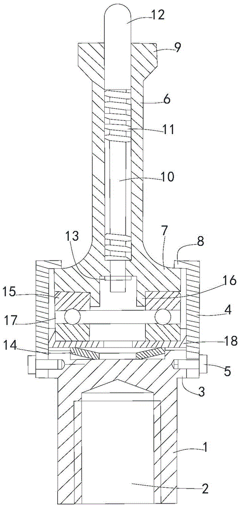
[0008] In order to make the technical means, creative features, goals and effects achieved by the present invention easy to understand, the present invention will be further elaborated below in conjunction with illustrations and specific embodiments.

[0009] Such as figure 1 As shown, the pressure transmission mechanism proposed by the present invention includes a connecting seat 1, the bottom of which is provided with a fixing hole 2, the connecting seat is installed on the frame through the fixing hole, the top of the connecting seat has a rim 3, and the rim is along the edge of the connecting seat. Set in the circumferential direction and protrude to the outside of the connecting seat, the connecting seat is provided with a sleeve 4, the bottom of the sleeve is covered on the outside of the edge, and connected by the set screw 5, the sleeve is provided with a guide cylinder 6, the guide cylinder The bottom edge has a limiting edge 7, which extends into the sleeve, and the ...


PUM


Abstract

The invention provides a novel pressure transmitting mechanism which comprises a connecting base, wherein an edge is arranged at the top of the connecting base; a sleeve is arranged on the connecting base; the bottom of the sleeve is covered on the outer side of the edge; a guiding drum is arranged in the sleeve; a limiting edge is arranged at the bottom edge of the guiding drum; the limiting edge extends into the sleeve; a ridge strip is arranged at the top edge of the sleeve; the limiting edge is blocked on the inner side of the ridge strip; a jacking rod is arranged in the guiding drum; a spring sleeves the jacking rod; a pressing head is arranged at the top of the jacking rod; a blocking edge is arranged on the inner side at the bottom end of the guiding drum; the blocking edge is raised toward the inner side of the sleeve; the top end of the spring is resisted against the pressing head; the bottom end of the spring is resisted against the blocking edge; the jacking rod extends out of the bottom of the guiding drum; a blocking ring is arranged at the bottom end of the jacking rod; the blocking ring and the spring are respectively arranged on the two sides of the blocking edge; an embedding slot is formed in the top of the connecting base; a disc spring is arranged in the embedding slot; an isolating ring is arranged above the disc spring; a connecting ring edge is arranged at the bottom end of the guiding drum; the isolating ring sleeves the connecting ring edge; a jacking plate is arranged on the middle part of the isolating ring; an end cover is arranged between the disc spring and the isolating ring; the end cover sleeves the bottom end of the isolating ring.

Description

technical field [0001] The invention relates to a novel pressure transmission mechanism. Background technique [0002] During the use of a kind of equipment, there is material placed on its supporting structure. The weight of the material needs to be monitored in real time in order to control the transmission of the material. A new type of pressure transmission mechanism is installed at the end of the weight monitoring device. The pressure transmission mechanism The sensitivity has an important influence on the smooth progress of the production process. The commonly used pressure transmission mechanism is inconvenient to install and is prone to failure. It is necessary to improve its structure to overcome the above defects. Contents of the invention [0003] The purpose of the present invention is to provide a new type of pressure transmission mechanism, which facilitates pressure transmission and reduces the occurrence of failures. [0004] The technical scheme that the...

Claims


Application Information

Patent Timeline
IPC IPC(8): B65G43/00
CPCB65G43/00
Inventor 吕彬
Owner ZHEJIANG ZHONGJI PILE IND
Features
  • R&D
  • Intellectual Property
  • Life Sciences
  • Materials
  • Tech Scout
  • Unparalleled Data Quality
  • Higher Quality Content
  • 60% Fewer Hallucinations
Learn More