
An intelligent electric control deceleration pier

A deceleration pier, electronic control technology, applied in the direction of roads, road signs, traffic signals, etc., can solve the problem that deceleration is not always needed, flexible setting deceleration piers, can not be achieved, etc., to achieve the overall structure is simple, easy to operate, avoid wiring harnesses The effect of constraints

Inactive Publication Date: 2016-08-24
SUZHOU HEXINMEI ELECTRONICS SCI & TECH CO LTD
View PDF9 Cites 0 Cited by
  • Summary
  • Abstract
  • Description
  • Claims
  • Application Information

AI Technical Summary

Problems solved by technology

[0004] To sum up, the various improved designs for the deceleration pier start from its structure to achieve the advantages of improving the actual installation efficiency, improving the deceleration effect, and ensuring driving safety. In fact, for the deceleration pier, its The setting is to play a deceleration effect on the vehicles driving on the road, but there is such a situation, the deceleration on some roads is not always needed, and the setting needs to be determined according to the actual situation, and the existing deceleration pier They are all directly fixed on the road surface. If you want to move again, it will become extremely troublesome. It is impossible to flexibly set the deceleration pier according to actual needs. This is the deficiency and shortcoming of the existing various deceleration piers. make further improvements

Method used


Image

  • An intelligent electric control deceleration pier
  • An intelligent electric control deceleration pier

Examples


Embodiment Construction

[0023] The specific implementation manners of the present invention will be further described in detail below in conjunction with the accompanying drawings.

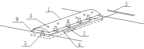
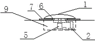
[0024] Such as figure 1 As shown, the present invention designs an intelligent electronically controlled deceleration pier, including a deceleration pier body 1, a control module 2, a power supply 3 connected to the control module 2, a wireless communication module 4, and at least two electrically controlled telescopic supports Device 5; the ground position of the deceleration pier body 1 is provided with a groove 9, the size of the groove 9 is adapted to the size of the deceleration pier body 1, the control module 2 is arranged in the groove 9, and each electronically controlled telescopic support device 5 The array is distributed on the bottom of the deceleration pier body 1, wherein the working end of each electrically controlled telescopic support device 5 is connected to the bottom of the deceleration pier body 1, ...


PUM


Abstract

The invention relates to an intelligent electronically controlled deceleration pier, which is improved and designed for the existing technology. By setting a groove for accommodating the deceleration pier body on the road surface, combined with an electronically controlled telescopic support device, and adopting an electronically controlled structure, it can effectively realize According to the actual needs of the road, the deceleration pier can be used flexibly, which overcomes the shortcomings of the existing deceleration pier after being fixed, and uses wireless mode to send the control signal, which makes the overall structure more concise, avoids the constraints of the wiring harness, and makes the actual use and control more convenient.

Description

technical field [0001] The invention relates to an intelligent electric control deceleration pier. Background technique [0002] The deceleration pier is a public facility arranged on the road, which is used to decelerate the vehicles on the road. The deceleration pier is mostly made of rubber material and protrudes from the road surface. With the extensive use of the deceleration pier in urban construction , designers and manufacturers are constantly proposing improved design schemes for deceleration piers in order to achieve better application effects, such as patent number: 201120509573.9, which discloses a new type of deceleration pier, which mainly includes a pier plate and a bottom plate, and the upper surface of the bottom plate There is a long concave mortise in the center of the pier, and the bottom plate is divided into two symmetrical half plates along the central axis of the long concave trough. A long I-shaped tenon is set in the center of the bottom of the pier...

Claims


Application Information

Patent Timeline
Patent Type & Authority Patents(China)
IPC IPC(8): E01F9/529E01F9/50
Inventor 朱霞高珺胡国良
Owner SUZHOU HEXINMEI ELECTRONICS SCI & TECH CO LTD
Learn More