
Display panel and display device

A display panel and display device technology, applied in nonlinear optics, instruments, optics, etc., can solve the problems of increasing the overall weight of the liquid crystal display device, increasing the overall thickness of the liquid crystal display device, and failing to realize the thinning of the liquid crystal display device.

Active Publication Date: 2015-02-18
BOE TECH GRP CO LTD
View PDF4 Cites 28 Cited by
  • Summary
  • Abstract
  • Description
  • Claims
  • Application Information

AI Technical Summary

Problems solved by technology

[0004] To sum up, the liquid crystal display devices in the prior art need to irradiate the display panel with the light emitted by the backlight module arranged behind the display panel to realize normal display, but due to the existence of the backlight module, not only increases The overall thickness of the liquid crystal display device is increased, and the overall weight of the liquid crystal display device is also increased, so it is impossible to realize the thinning of the liquid crystal display device

Method used


Image

  • Display panel and display device
  • Display panel and display device
  • Display panel and display device

Examples


Embodiment Construction

[0027] The specific implementation manners of the present invention will be further described in detail below in conjunction with the accompanying drawings and embodiments. The following examples are used to illustrate the present invention, but are not intended to limit the scope of the present invention.

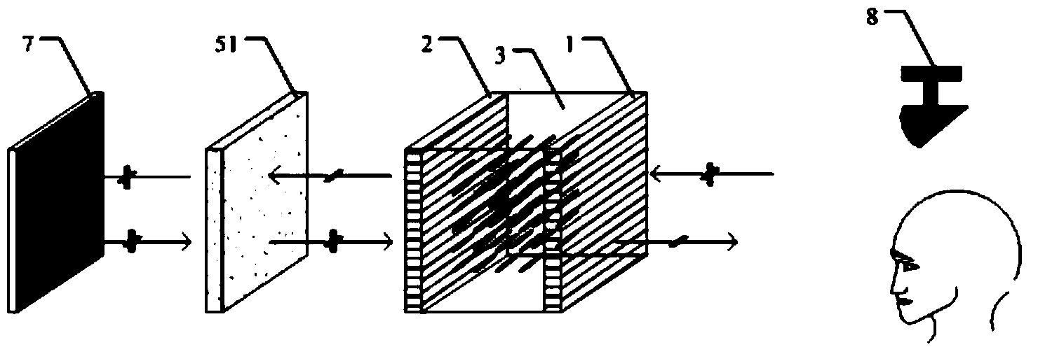
[0028] figure 1 It is a schematic diagram of a display panel provided by an embodiment of the present invention, the display panel includes an upper polarizer 1, a lower polarizer 2, and a liquid crystal layer 3 arranged between the upper polarizer 1 and the lower polarizer 2 and An array substrate 4, a plurality of pixel units are arranged on the array substrate 4, and each pixel unit has a plurality of sub-pixel units displaying different colors, wherein the display panel also includes The quantum dot layer 5 on one side of the liquid crystal layer 3 emits light when excited by external light. For example, the external light may be ultraviolet light.

[0029] In the d...


PUM

PropertyMeasurementUnit
particle diameteraaaaaaaaaa

Abstract

The invention discloses a display panel and a display device. The display panel comprises an upper polarizer, a lower polarizer, a liquid crystal layer and an array substrate, wherein the liquid crystal layer and the array substrate are arranged between the upper polarizer and the lower polarizer, a plurality of pixel units are arranged on the array substrate, and each pixel unit is provided with a plurality of subpixel units displaying different colors. The display panel further comprises a quantum dot layer, wherein the quantum dot layer is arranged on the side, far from the liquid crystal layer, of the lower polarizer, and light is emitted by the quantum dot layer through the excitation of external light. According to the display panel displayed by the invention, light is emitted by the quantum dot layer through the excitation of external light, so that a light source does not need to be provided by a backlight module structure, and the lightening and thinning of the display device are realized.

Description

technical field [0001] The present invention relates to the field of display technology, in particular to a display panel and a display device. Background technique [0002] The existing Liquid Crystal Display (LCD for short) includes a backlight module and a display panel. The backlight module provides sufficient brightness and evenly distributed light sources, so that images can be normally displayed on the display panel. [0003] The backlight modules in the prior art are roughly divided into two types: direct-type and side-type. Among them, the direct-type backlight module is to place the light source under the light guide plate, and the optical film materials of each layer of the light guide plate, such as the diffusion sheet and the bottom enhancement. sheet, top enhancement sheet, prism sheet, etc.; the side-entry backlight module is to place the light source on the side of the light guide plate, and an optical film is also arranged above the light guide plate. [00...

Claims


Application Information

Patent Timeline
Patent Type & Authority Applications(China)
IPC IPC(8): G02F1/13357G02F1/1335
CPCG02F1/133528G02F1/1336G02F1/133614G02F1/133618
Inventor 王尚
Owner BOE TECH GRP CO LTD
Learn More