Self-adaptation stepping type angular displacement piezoelectric actuator and method

A piezoelectric actuator, step-by-step technology, applied in piezoelectric effect/electrostrictive or magnetostrictive motors, generators/motors, electrical components, etc., can solve the problem that the actuator cannot be used, piezoelectric Problems such as small heap output stroke and reduced application range

Active Publication Date: 2015-02-18
XI AN JIAOTONG UNIV
View PDF6 Cites 7 Cited by
  • Summary
  • Abstract
  • Description
  • Claims
  • Application Information

AI Technical Summary

Problems solved by technology

[0002] Piezoelectric actuators are widely used in many fields, such as aerospace, automotive engineering, etc., because of their small size, large power, and precise micro-displacement characteristics. The output displacement has a high resolution. It has excellent characteristics. With the development of science and technology, the requirements for piezoelectric actuators are getting higher and higher. Many fields not only require high displacement resolution and large driving force, but also require a large range of displacement. output, but the existing piezoelectric stack output stroke is very small, and can only output linear displacement, and the corresponding installation structure has high machining accuracy requirements, and very small machining errors may cause the entire actuator to be unusable , so the scope of application is greatly reduced

Method used


Image

  • Self-adaptation stepping type angular displacement piezoelectric actuator and method
  • Self-adaptation stepping type angular displacement piezoelectric actuator and method
  • Self-adaptation stepping type angular displacement piezoelectric actuator and method

Examples


Embodiment Construction

[0017] The present invention will be described in further detail below in conjunction with the accompanying drawings and specific embodiments.

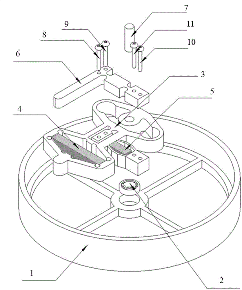
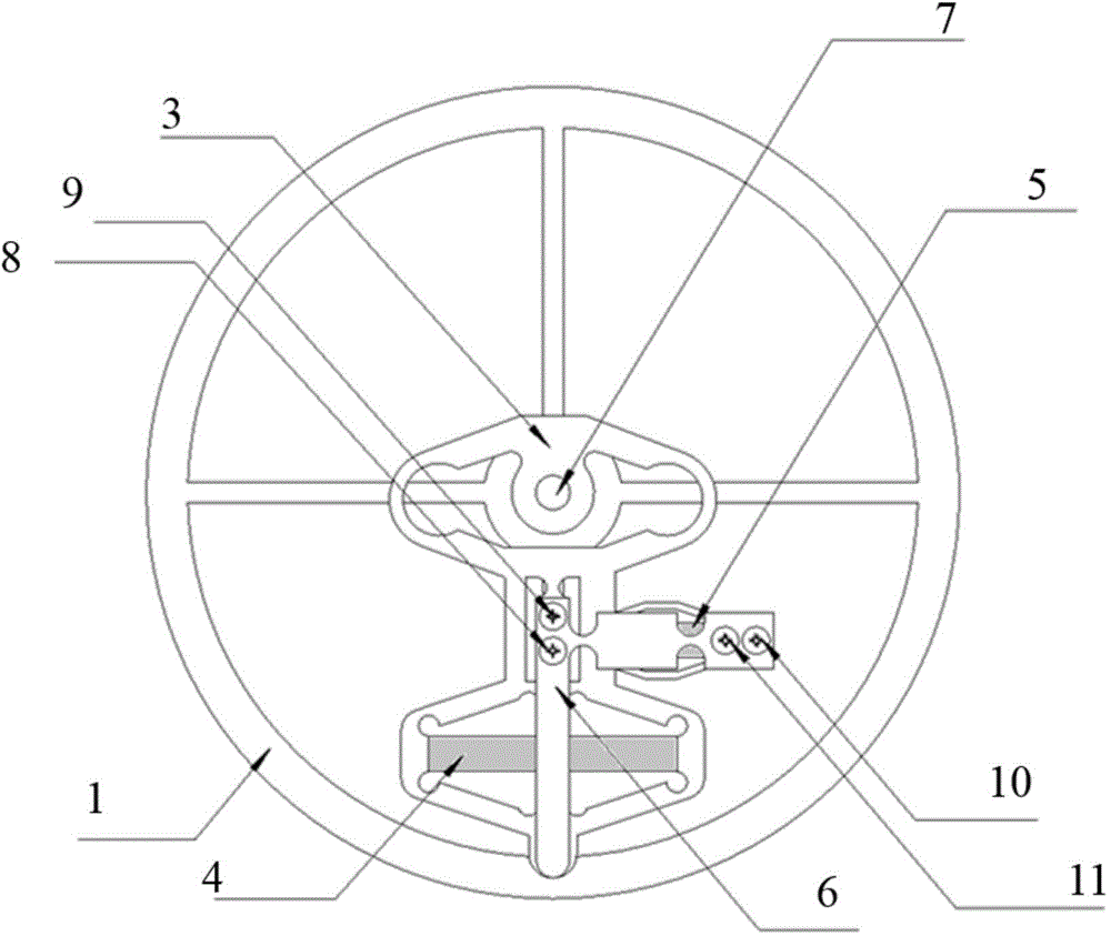
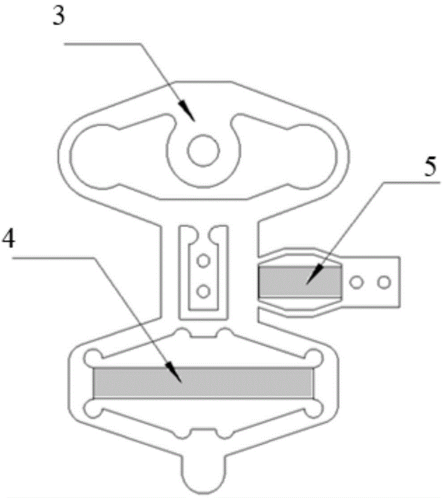
[0018] Such as figure 1 and figure 2 As shown, an adaptive stepping angular displacement piezoelectric actuator of the present invention includes a circular track base 1, a precision bearing 2 located in the center hole of the circumferential track base 1, and an adaptive adjustment arm 3 located on the precision bearing 2 , and the center hole of the self-adaptive regulating arm 3 is centered with the position of the precision bearing 2, the upper end of the self-adaptive regulating arm 3, that is, the position of the central hole, is a diamond-shaped elastic structure, the middle part is a flexible hinge mechanism, and the lower end is a lower diamond-shaped displacement amplification mechanism, the first piezoelectric ceramic driver 4 used for clamping is set in the lower diamond-shaped displacement amplification mechanism, the m...


PUM


Abstract

A self-adaptation stepping type angular displacement piezoelectric actuator comprises a circumferential rail base, a precision bearing, a self-adaptation adjusting arm, a first piezoelectric ceramic driver and a second piezoelectric ceramic driver. The precision bearing is arranged in a central hole of the circumferential rail base, the first piezoelectric ceramic driver is arranged in the self-adaptation adjusting arm and used for clamping, and the second piezoelectric ceramic driver is arranged in the self-adaptation adjusting arm and used for driving. A right-angle arm is fixedly connected with a flexible hinge in the self-adaptation adjusting arm and the output end of a second piezoelectric stack, one end of an output shaft is fixed to an inner ring of the precision bearing, and the other end of the output shaft is fixed to the central hole of the self-adaptation adjusting arm. Linear displacement can be converted into angular displacement by adopting only two piezoelectric stacks, meanwhile, the two piezoelectric ceramic drivers are coordinated to move according to a certain rule and rotate in a stepping mode, therefore, the aim of outputting large-travel angular displacement is achieved, clockwise rotation and anticlockwise rotation can be achieved, and structural complexity is reduced greatly. In addition, the inner size can be adjusted in a self-adaptation mode under the condition of machining errors through the self-adaptation adjusting structure.

Description

technical field [0001] The invention belongs to a piezoelectric ceramic driving device, in particular to an adaptive stepping angular displacement piezoelectric actuator and method. Background technique [0002] Piezoelectric actuators are widely used in many fields, such as aerospace, automotive engineering, etc., because of their small size, large power, and precise micro-displacement characteristics. The output displacement has a high resolution. With the development of science and technology, the requirements for piezoelectric actuators are getting higher and higher. In many fields, not only high displacement resolution and large driving force are required, but also a large range of displacement is required. output, but the existing piezoelectric stack output stroke is very small, and can only output linear displacement, and the corresponding installation structure has high machining accuracy requirements, and very small machining errors may cause the entire actuator to ...

Claims


Application Information

Patent Timeline
IPC IPC(8): H02N2/02
Inventor 武彤晖徐明龙敬子建苗维凯
Owner XI AN JIAOTONG UNIV
Why Eureka
Try Eureka