Check patentability & draft patents in minutes with Patsnap Eureka AI!

Electromagnetic positioning device

一种调节设备、电磁的技术,应用在电磁体、磁体、电路等方向,能够解决限制衔铁单元附着力等问题,达到改进运动特性或动力学特性的效果

Active Publication Date: 2015-02-18
ETO MAGNETIC GMBH
View PDF6 Cites 2 Cited by
  • Summary
  • Abstract
  • Description
  • Claims
  • Application Information

AI Technical Summary

Problems solved by technology

[0004] The cited technical design of the same type as the present invention also has other drawbacks requiring improvement, limiting the holding of the armature unit in the de-energized stop state (typically in the retracted state of the push rod unit). Adhesion on core area

Method used


Image

  • Electromagnetic positioning device
  • Electromagnetic positioning device
  • Electromagnetic positioning device

Examples


Embodiment Construction

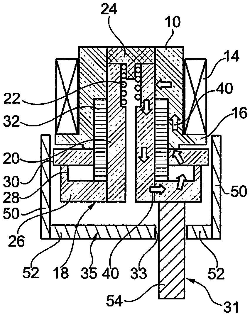
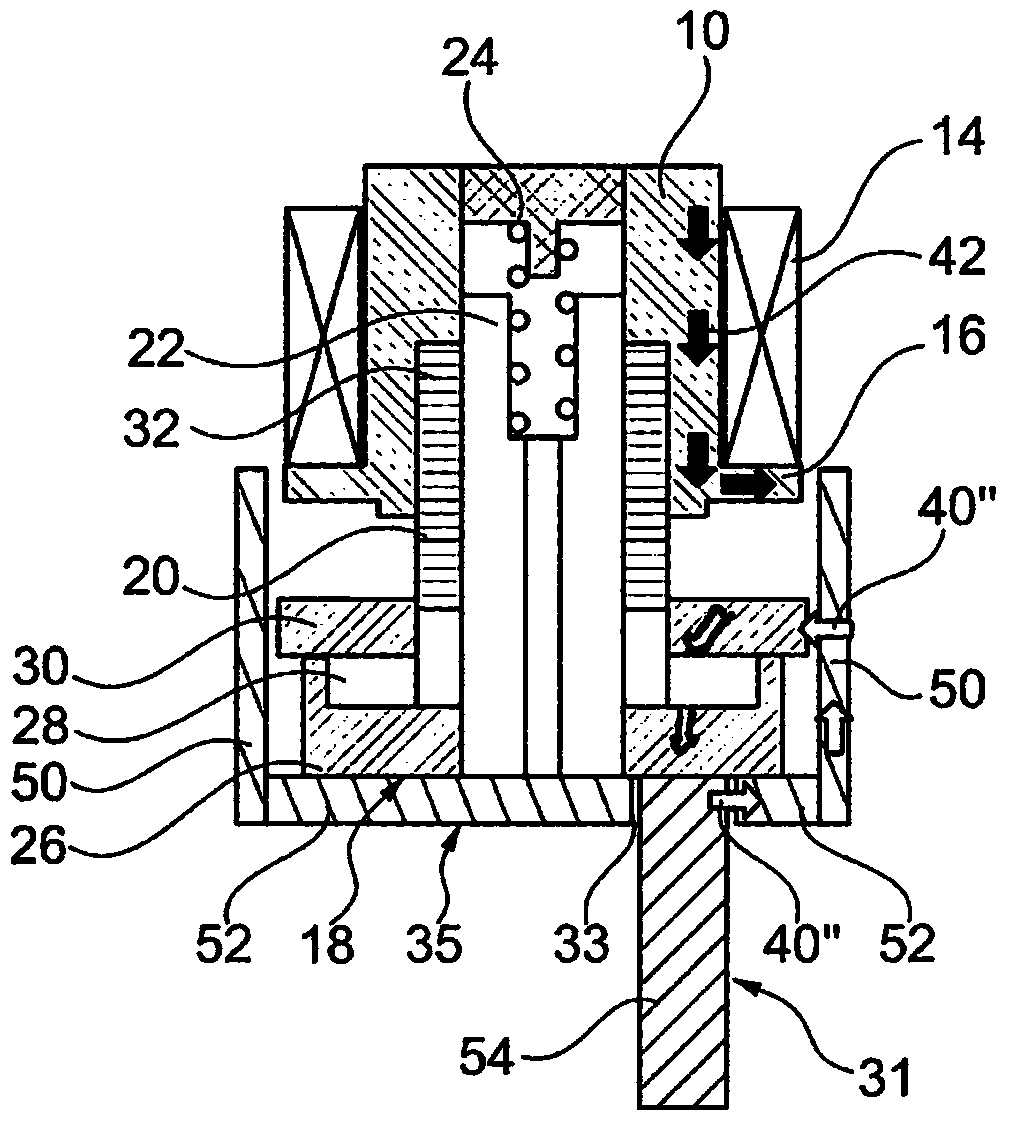
[0022] Figures 1 to 3 In a preferred embodiment of the invention, a longitudinal section through the electromagnetic adjusting device according to the invention is shown, the reference numerals being used for all illustrations.

[0023] According to a technical design of the type indicated in DE 20 2009 010 495, the radially symmetrically constructed device consists of a fixed (ie assembled and not movable per se) core unit 10 which forms a base section 12 on the end side , and is surrounded on the outer peripheral surface by the coil unit 14 held on the (not shown) coil carrier.

[0024] The armature unit 18 can be drawn into the core unit 10 which is widened on the end side opposite the bottom section 12 by means of the flange region 16 by means of a shaft section 20 , wherein the shaft section has an axis in the direction of the bottom section 12 Towards the radial widening 22 of the perforation, a coil spring 24 is arranged in this widening, which prestresses the armatur...


PUM


Abstract

The invention relates to an electromagnetic positioning device having an armature unit (18) that can be actuated as a reaction to a current supply of a stationary coil unit (14) relative to a stationary core unit (10), which armature unit has permanent-magnetic means (28) and a tappet unit (31) that is led out of a magnetically flow-conducting housing (35), wherein on the shell side of a shaft section (20) of the armature unit (18) magnetically non-conducting socket means (32) are provided in such a way that in a state of the coil unit (14) in which no current is supplied a permanent-magnetic flow (40) of the permanent-magnet means (28) flows through the core unit (10) and the shaft section (20) for retaining the armature unit (18) on the core unit (10) and in a state of the coil unit (14) in which current is supplied the permanent-magnetic flow (40', 40") is displaced from the core unit (10) into a housing section (50, 52) of the housing and a permanent-magnetic flow circuit is closed via a section (54) of the tappet unit on the housing side.

Description

technical field [0001] The invention relates to an electromagnetic adjustment device according to the preambles of the independent claims. Background technique [0002] Such devices are generally known for solving various control tasks, for example in connection with internal combustion engines, and are manufactured in large numbers. German utility model 20 2009 010 495 of the applicant shows an electromagnetic adjustment device of this type, which is assumed to be of the same type as the present invention, in which, as the longitudinal push rod of the push rod unit element of the multi-part armature unit, it is also designed Being radially symmetrical, the push rod can be driven to move relative to the fixed iron core unit by energizing the fixed coil unit. The pushrod unit also engages end-to-end into the adjustment counterpart, in the exemplary embodiment into a recess which serves for the adjustment of the camshaft of the internal combustion engine. [0003] A device o...

Claims


Application Information

Patent Timeline
Patent Type & Authority Applications(China)
IPC IPC(8): H01F7/06
CPCH01F7/122H01F7/1615H01F7/1623
Inventor T.格尔兹
Owner ETO MAGNETIC GMBH
Features
  • R&D
  • Intellectual Property
  • Life Sciences
  • Materials
  • Tech Scout
  • Unparalleled Data Quality
  • Higher Quality Content
  • 60% Fewer Hallucinations
Learn More