A gas-liquid separator

A technology of gas-liquid separator and gas-liquid separation section, which is applied in the direction of separation method, dispersed particle separation, gas fuel, etc., and can solve the problems such as the reduction of liquid storage space of the separator, the large working range of the separator, and the failure to operate normally. To achieve the effect of improving stability and improving the efficiency of gas-liquid separation

Active Publication Date: 2017-01-18
PETROCHINA CO LTD
View PDF8 Cites 2 Cited by
  • Summary
  • Abstract
  • Description
  • Claims
  • Application Information

AI Technical Summary

Problems solved by technology

Conventional separators have the following two problems: First, the setting of the separation element greatly reduces the liquid storage space of the separator. When facing a slug flow in the gas production pipeline, the liquid quickly enters the separator, and the separator cannot meet the storage requirements. , the liquid will be brought into the downstream pipeline, so that the downstream compressor and other equipment cannot operate normally, affecting the normal production of the station; the second is that the change of pressure with the season or production period makes the operating condition range of the separator wide, and the conventional separator Difficult to achieve ideal separation effect

Method used


Image

  • A gas-liquid separator
  • A gas-liquid separator

Examples


Embodiment 1

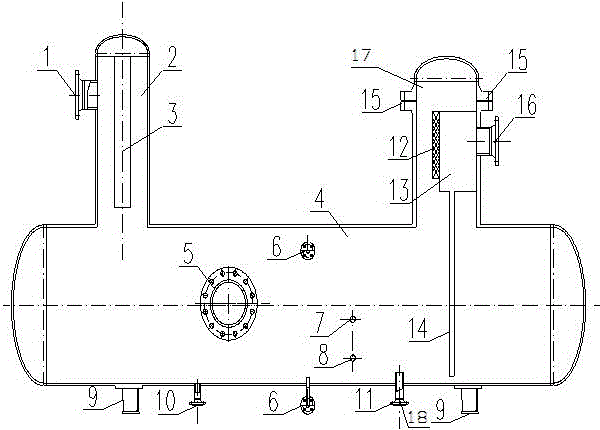
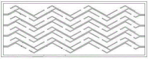
[0018] Such as figure 1 As shown, a gas-liquid separator includes a liquid storage chamber 4, a cyclone separation section 2 and a deep gas-liquid separation section 17 arranged on the top of the liquid storage chamber 4 and communicating with it, and the bottom of the liquid storage chamber 4 is provided with Base 9, described cyclone separation section 2 is provided with gas-liquid separator inlet 1, is provided with cyclone post 3 in described cyclone separation section 2; Described depth gas-liquid separation section 17 is provided with separator outlet 16 , the inner end face of the separator outlet 16 is provided with a blade type separation box 13, the lower end of the blade type separation box 13 is connected with a blade type separation box discharge pipe 14 leading to the liquid storage chamber 4, the blade type separation box 13 The other end relative to the separator outlet 16 is provided with a wire mesh demister 12, and the wire mesh demister 12 communicates wit...

Embodiment 2

[0025] On the basis of the above-mentioned embodiment 1, the inspection drain port 10, the inspection port 5 and the flange 15 are set up for the convenience of maintenance; the normal drain of the separator is carried out through the drain port 11, and its automatic drain is carried out through the liquid level measurement 6 , high liquid level switch 7, and low liquid level switch 8 are used to set the switch of the automatic liquid discharge valve; the liquid separated by the vane type separation box is connected to the liquid storage chamber through the liquid discharge pipe of the vane type separation box to prevent secondary entrainment. The liquid storage chamber 4 is also provided with a liquid level gauge interface 6 for installing a liquid level gauge, a high liquid level switch 7, a low liquid level switch 8, and an automatic liquid discharge valve 18 is installed in the production liquid discharge port 11. , the liquid level gauge interface 6, high liquid level swit...

Embodiment 3

[0027] On the basis of the above-mentioned embodiment 2, the liquid storage chamber 4 is also provided with an inspection port 5 and an inspection drain port 10. The inspection drain port 10 is provided for the daily maintenance of the separator, and the drain port is flush with the bottom of the tube. , to ensure that all liquid is drained.


PUM


Abstract

The invention provides a novel gas-liquid separator comprising a liquid storage cavity, and a cyclone separation section and a deep gas-liquid separation section which are arranged at the top of the liquid storage cavity and are communicated with the liquid storage cavity, wherein a base is arranged at the bottom of the liquid storage cavity, a gas-liquid separator inlet is formed in the cyclone separation section, and a cyclone column is arranged in the cyclone separation section; a separator outlet is formed in the deep gas-liquid separation section, a blade type separation box is arranged on the inner end surface of the separator outlet, the lower end of the blade type separation box is connected with a blade type separation box liquid discharge pipe which is communicated with the liquid storage cavity, the other end of the blade type separation box, relative to the separator outlet, is provided with a wire mesh demister, and the wire mesh demister is communicated with the blade type separation box; and a production liquid discharge opening is also formed in the bottom of the liquid storage cavity. The novel gas-liquid separator provided by the invention can be used for greatly improving the operation stability of gas fields, and re-purification of gas is achieved so as to ensure that gas to be purified is subjected to deep gas-liquid separation; and the purpose of increasing the gas-liquid separation efficiency of a multi-stage baffle plate liquid removal component can be achieved.

Description

technical field [0001] The invention relates to a gas-liquid separator, in particular to a separator for gas-liquid separation at a gathering and transportation station in the petroleum and natural gas exploitation industry. Background technique [0002] During the development of natural gas fields, because some gas wells have high water production and contain a certain amount of condensate oil and other impurities, gas-liquid separation needs to be carried out at the gas gathering station. In the development of some gas fields, due to the needs of the gas gathering process, the operating pressure of the station will vary greatly with the change of the season or production period. At the same time, considering the development cost of the gas field, the gas gathering station is generally only equipped with a gas-liquid separator. (hereinafter referred to as the separator), the separation element is set in the separator to improve the separation efficiency. Conventional separ...

Claims


Application Information

Patent Timeline
Patent Type & Authority Patents(China)
IPC IPC(8): B01D50/00C10L3/10
Inventor 王登海胡建国郑欣刘银春刘峰杨家茂何茂林杨光贾海海
Owner PETROCHINA CO LTD
Why Eureka
Try Eureka