
Motorized spindle of aerostatic bearing

A technology of aerostatic bearing and electric spindle, which is applied in the direction of large fixed members, metal processing machinery parts, maintenance and safety accessories, etc., can solve the problems of affecting processing accuracy, poor ball roundness, large vibration, etc., to improve work efficiency , Improve the cooling effect, improve the effect of operating accuracy

Inactive Publication Date: 2015-02-25
东莞市科隆电机有限公司
View PDF8 Cites 6 Cited by
  • Summary
  • Abstract
  • Description
  • Claims
  • Application Information

AI Technical Summary

Problems solved by technology

[0002] At present, as the diameter of the hole that needs to be processed on the PCB main board is getting smaller and smaller, the density is getting higher and higher, the requirements for machining accuracy are getting higher and higher, and the requirements for the speed and accuracy of the electric spindle are becoming more and more strict. Traditional electric spindle bearings The line speed is slow and the roundness of the ball is poor, which leads to the vibration of the electric spindle at high speed, which affects the machining accuracy.

Method used


Image

  • Motorized spindle of aerostatic bearing
  • Motorized spindle of aerostatic bearing
  • Motorized spindle of aerostatic bearing

Examples


Embodiment Construction

[0028] The present invention will be further described below in conjunction with the accompanying drawings and specific embodiments.

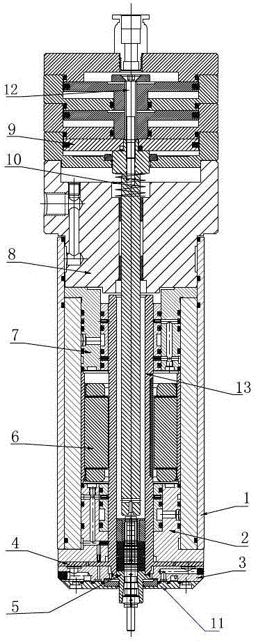
[0029] Aerostatic bearing electric spindle, including coaxially arranged main body assembly 1, shaft core 13, front bearing assembly 2, rear bearing assembly 7, thrust bearing 3, stator assembly 6, rotor assembly 5, water / air passage sleeve assembly 8 and Cylinder assembly 9; wherein: the rear end of the rotor assembly 5 is connected to the cylinder assembly 9, and on the periphery of the rotor assembly 5 there are water / air line sleeve assembly 8, rear bearing assembly 7, stator assembly 6 and front bearing assembly 2 in sequence from back to front , on the periphery of the rotor assembly 5, in the rear bearing assembly 7, the stator assembly 6 and the front bearing assembly 2, a shaft core 13 is provided, the front portion of the shaft core 13 has an outwardly protruding edge, and the edge is a flying disc, The flying disc is connected to the...


PUM


Abstract

The invention belongs to the field of machining, relates to a machining device and discloses a motorized spindle of an aerostatic bearing. The motorized spindle comprises a main component, a front bearing component, a rear bearing component, a thrust bearing, a stator component, a rotor component, a water / gas circuit sleeve component and an air cylinder component; the front bearing component is arranged at the front end of the main component and extend into the same to be flush with the outer edge of the main component, the front end of the front bearing component is connected with the rotor component which is externally connected with the thrush component, and a thrust clearance ring is arranged between the thrust bearing and the front bearing component; the front bearing component is backwardly connected with the stator component in a main component cavity, the rear end of the stator component is connected with the rear bearing component in the main component cavity, the narrower front part of the water / gas circuit sleeve component extends into the main component cavity to be connected with the rear bearing component while the rear end of the water / gas circuit sleeve component is connected with the air cylinder component, and the rear end of the air cylinder component is provided with a screw penetratingly connected with the air cylinder component. The motorized spindle is high in rotation speed, good in stability and high in machining precision.

Description

technical field [0001] The invention belongs to the field of mechanical processing and relates to an electric spindle. Background technique [0002] At present, as the diameter of the aperture that needs to be processed on the PCB motherboard is getting smaller and smaller, the density is getting higher and higher, the requirements for machining accuracy are getting higher and higher, and the requirements for the speed and accuracy of the electric spindle are becoming more and more strict. The traditional electric spindle bearings The line speed is slow and the roundness of the ball is poor, which leads to the vibration of the electric spindle at high speed, which affects the machining accuracy. Contents of the invention [0003] The purpose of the present invention is to provide an electric spindle with air static pressure bearing, which can make up for the shortcomings of the existing problems and realize high stability of the electric spindle when it runs at high speed....

Claims


Application Information

Patent Timeline
Patent Type & Authority Applications(China)
IPC IPC(8): B23B19/02B23Q11/12
CPCB23Q1/70B23Q11/126
Inventor 陈文生简相华
Owner 东莞市科隆电机有限公司
Learn More