A multi-roller laser transmission welding clamping device

A technology of laser transmission welding and clamping device, which is applied in the field of multi-roller laser transmission welding clamping device and laser transmission welding clamping device, which can solve the problems of glass ball surface wear, inability to realize three-dimensional weld seam welding, stress concentration, etc. , to improve the quality of

Inactive Publication Date: 2016-08-24
JIANGSU UNIV
View PDF8 Cites 1 Cited by
  • Summary
  • Abstract
  • Description
  • Claims
  • Application Information

AI Technical Summary

Problems solved by technology

The disadvantage is that only some planar welds (that is, the surface is required to be flat) can be welded, and the welding of three-dimensional welds cannot be realized, but the application of three-dimensional weldments in practical applications is more and more
Secondly, the patent "laser transmission welding follow-up clamping device", the application number is: 201210462627.X, although the device can realize the welding of three-dimensional welds, but the clamping force is not uniform, according to related research, during the welding process, the compression The size and uniformity of the force have a great influence on the quality of the weldment
Furthermore, the Globo welding device invented by Leister is more ingenious. Its welding head has a glass ball. This glass ball can not only focus the laser beam, but also exert a pressing force. Its main advantage is that it can realize any three-dimensional welding seam welding, and the structure is compact, but it uses a single point of contact, which can easily lead to stress concentration after welding. In addition, the long-term rolling friction of the glass ball will easily cause the surface of the glass ball to wear and make the optical performance of the glass ball worse. Therefore, it is urgently needed A device that overcomes these disadvantages

Method used


Image

  • A multi-roller laser transmission welding clamping device
  • A multi-roller laser transmission welding clamping device
  • A multi-roller laser transmission welding clamping device

Examples


Embodiment Construction

[0024] The present invention will be further described below in conjunction with the accompanying drawings and embodiments.

[0025] Such as Figure 1-6 shown.

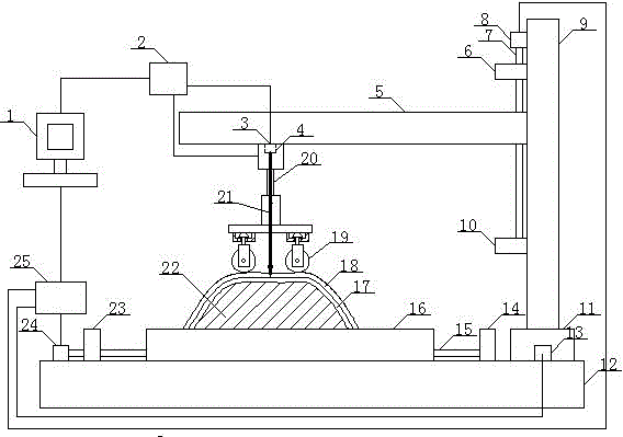
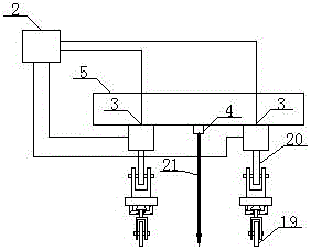
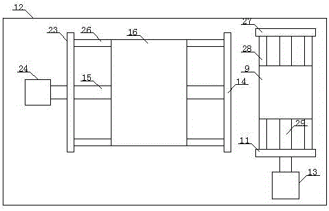
[0026] A multi-roller type laser transmission welding clamping device, which includes a PC machine 1, a stepper motor control system 25, X, Y, Z axis feed system and laser head 4, a pressure applying mechanism and a pressing mechanism, such as figure 1 , 2 shown.

[0027] in:

[0028] The X-axis feed mechanism is: the stepping motor control system 25 controls the stepping motor 24 in the X-axis direction, the stepping motor 24 in the X-axis direction drives the screw rod 15 in the X-axis direction, and the screw rod 15 in the X-axis direction drives the workbench 16 Moving in the X-axis direction, the upper workpiece 18, the lower workpiece 17 and the bottom mold 22 are installed on the workbench 16 according to the order from top to bottom. The screw rod 15 in the axial direction is parallel, the screw rod 15 in...


PUM


Abstract

A multi-roller laser transmission welding clamping apparatus used between thermoplastic plastics or between a thermoplastic plastic and a metal material comprises a PC machine, a stepper motor control system, an X, Y, Z-axis feeding system and a laser head, and also comprises a pressing mechanism and a clamping mechanism; a hydraulic control system regulates a hydraulic small thimble to make the sum of the downward pressing forces of two rollers of each group of rollers equal to pre-pressing force and the two downward pressing forces equal to each other; a bed die and a movable pressing device in the pressing mechanism cooperate with each other to clamp an upper workpiece and a lower workpiece in order to realize a curved workpiece; and the stepper motor control system controls laser to move along a predetermined route in order to realize welding of the curved workpiece. The laser transmission welding clamping apparatus of the thermoplastic plastic can realize welding of the curved workpiece, can accurately control the welding path and the pressing force, improves the overall strength and rigidity of a welded piece, avoids single point contact by adopting multi-roller pressing, and improves the quality of the processed workpiece.

Description

technical field [0001] The invention relates to the field of laser transmission welding, in particular to a clamping device for laser transmission welding between thermoplastics or between thermoplastics and metal materials, in particular to a multi-roller type laser transmission welding clamping device. Background technique [0002] Plastic products have the advantages of light weight, high strength, low density, low cost, excellent elasticity, and corrosion resistance. Therefore, plastics are used more and more widely, especially thermoplastics. Most thermoplastic products are molded products. Affected by injection molding, extrusion processing technology and mold making, many plastic products with irregular shapes or complex structures are difficult to be injection molded at one time. Usually the most economical and effective method is Combining multiple simple injection molded parts, a variety of joining methods for thermoplastics have emerged. Traditional mechanical co...

Claims


Application Information

Patent Timeline
Patent Type & Authority Patents(China)
IPC IPC(8): B29C65/16
Inventor 刘会霞蒋海荣李品严长王霄
Owner JIANGSU UNIV
Why Eureka
Try Eureka