
Mining multifunctional self-stirring grouting device and control method thereof

A self-stirring grouting and multi-functional technology, which is applied in safety devices, mining equipment, earthwork drilling and mining, etc., can solve problems such as grouting work cannot be carried out normally, fire extinguishing powder is easy to stick into blocks, pumps and pipelines are blocked, etc. , to achieve the effect of reducing labor intensity, reasonably controlling the amount of powder ingredients, and eliminating pipeline blockage

Inactive Publication Date: 2015-02-25
ANHUI UNIVERSITY OF ARCHITECTURE
View PDF5 Cites 1 Cited by
  • Summary
  • Abstract
  • Description
  • Claims
  • Application Information

AI Technical Summary

Problems solved by technology

Among them, manual mixing, the workers breathe the fire extinguishing powder during the stirring process, which is easy to cause harm to the body. At the same time, manual operation is all based on experience. The fire extinguishing powder is easy to stick into pieces and unevenly distributed, resulting in frequent blockage of pumps and pipelines, resulting in grouting work. unable to carry out normally
On the other hand, the grouting pump is an electrical device, and it cannot be grouted in the underground area without circuits or when the power is cut off. At the same time, there are certain safety hazards in live operation.

Method used


Image

  • Mining multifunctional self-stirring grouting device and control method thereof

Examples


Embodiment Construction

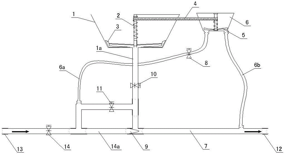
[0016] see figure 1 , the structural form of the mine-used multifunctional self-stirring grouting device in this embodiment is:

[0017] An ejector 9 is provided, the nozzle side of the ejector 9 is connected to the main liquid supply valve 14 through the liquid supply pipe 14a, the inlet of the main liquid supply valve 14 is the inlet 13 of the downhole high-pressure source, and the outlet of the ejector 9 passes through The slurry discharge pipe 7 is connected to the slurry outlet 12, and the lower material pipe 1a is connected between the suction port of the ejector 9 and the powder outlet of the lower material box 1, and the spiral screw is vertically arranged in the lower material box 1. A stirring knife 2, a fan blade stirring knife 3 is arranged at the lower end of the spiral stirring knife 2;

[0018] A liquid supply tank 6 is set, the liquid inlet at the bottom of the liquid supply tank 6 communicates with the liquid supply pipe 14a through the liquid inlet pipe 6a, ...


PUM


Abstract

The invention discloses a mining multifunctional self-stirring grouting device and a control method thereof. The mining multifunctional self-stirring grouting device is characterized by being provided with an ejector, wherein a nozzle side of the ejector is connected with a liquid supply main valve through a liquid supply pipe; an inlet of the liquid supply main valve is an underground high-pressure source access port; an outlet of the ejector is connected with a slurry outlet through a slurry discharge pipe; a suction inlet of the ejector is communicated with a powder outlet of a discharge box through a discharge pipe; a spiral stirring knife is vertically arranged in the discharge box; a blade stirring knife is arranged at the lower end of the spiral stirring knife; a liquid supply box is arranged; a liquid inlet in the bottom of the liquid supply box is communicated with the liquid supply pipe through a liquid inlet pipe; a liquid outlet in the bottom of the liquid supply box is communicated with the slurry discharge pipe; the liquid supply box is provided with an impeller and an impeller shaft rotating along with the impeller; a transmission chain is arranged between the impeller shaft and the spiral stirring knife; and the rotation of the spiral stirring knife is driven by the impeller through the transmission chain. The discharge quantity is controlled through the change of the liquid supply quantity, and the burdening is more uniform, so that the blockage phenomenon of viscous masses and pipelines is eliminated, and the slurry dissolution effect is effectively improved.

Description

technical field [0001] The invention relates to a device and a control method for realizing uniform self-stirring of fire-preventing powder by utilizing air-water pipeline pressure and mechanical transmission during fire-prevention grouting in coal mines. Background technique [0002] Grouting is often used to prevent natural fire in underground coal seams in coal mines, and the stirring and injection of anti-fire extinguishing powder are mainly divided into two steps: manual stirring and grouting pump injection. Among them, manual mixing, the workers breathe the fire extinguishing powder during the stirring process, which is easy to cause harm to the body. At the same time, manual operation is all based on experience. The fire extinguishing powder is easy to stick into pieces and unevenly distributed, resulting in frequent blockage of pumps and pipelines, resulting in grouting work. Unable to proceed normally. On the other hand, the grouting pump is an electrical device, a...

Claims


Application Information

Patent Timeline
IPC IPC(8): E21F5/00
CPCE21F5/00
Inventor 卢平余陶王厚良肖峻峰穆朝云马进戚宇涵
Owner ANHUI UNIVERSITY OF ARCHITECTURE
Learn More