
Engine control method and engine control system

A control method and control system technology, applied in the direction of engine control, combustion engine, machine/engine, etc., can solve the problems of not providing engine power and efficiency, increasing engine cost and complexity, etc., to reduce the risk of turbine failure, shorten Calibrated duty cycle, good reliability effect

Inactive Publication Date: 2015-02-25
GARRETT TRANSPORATION I INC
View PDF4 Cites 6 Cited by
  • Summary
  • Abstract
  • Description
  • Claims
  • Application Information

AI Technical Summary

Problems solved by technology

While recirculation or discharge valves are effective in preventing surge conditions, backflow valves typically provide no improvement in engine power and efficiency, while still adding cost and complexity to the engine

Method used


Image

  • Engine control method and engine control system
  • Engine control method and engine control system
  • Engine control method and engine control system

Examples


Embodiment Construction

[0015] Some embodiments of the inventions will now be described more fully hereinafter with reference to the accompanying drawings, in which some, but not all embodiments of the inventions are shown. Indeed, various embodiments of the invention may be embodied in different ways and should not be construed as limited to the embodiments described herein. The same reference numerals denote the same elements throughout. In the following detailed description, embodiments are described in sufficient detail to enable those skilled in the art to practice the invention. It is understood that other embodiments may be utilized without departing from the scope of the present invention. The following detailed description should therefore not be read in a limiting sense.

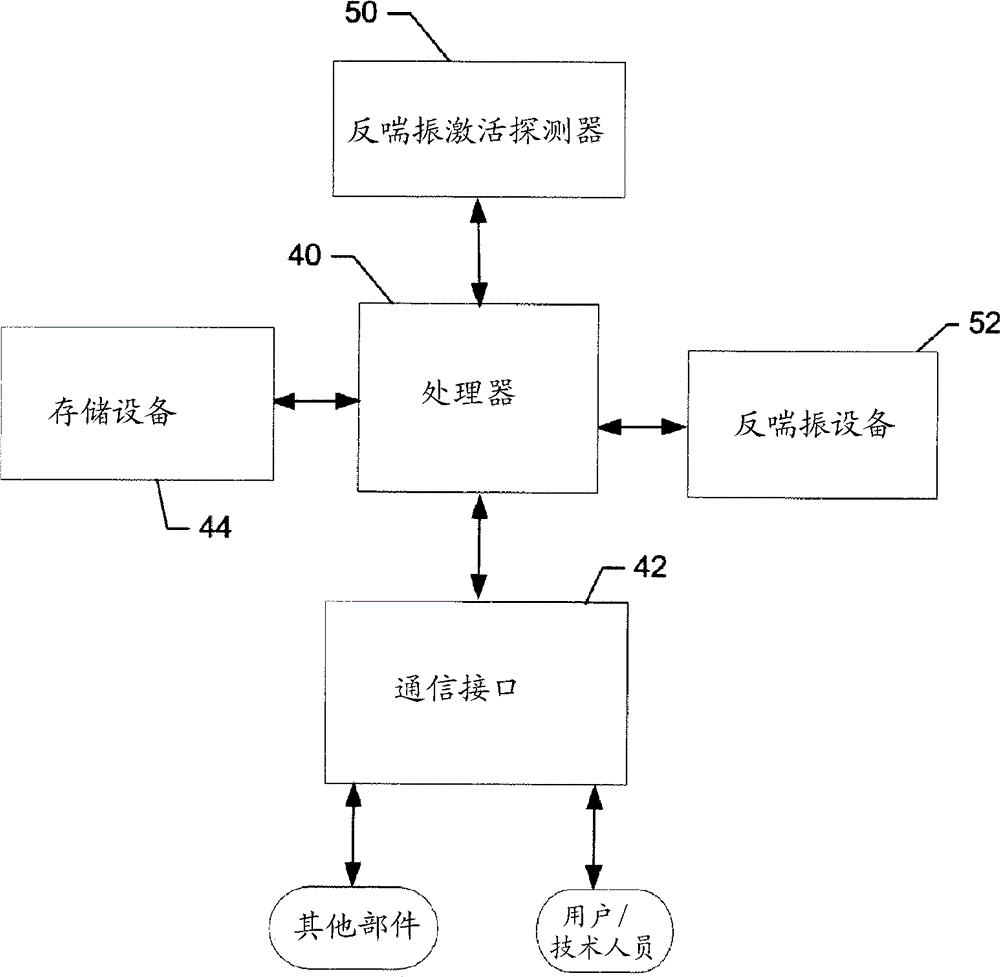
[0016] now refer to figure 1 , an example block diagram illustrating certain elements of a system including an engine control unit according to an example embodiment of the present invention is provided. However, fig...


PUM


Abstract

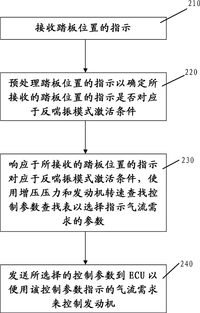
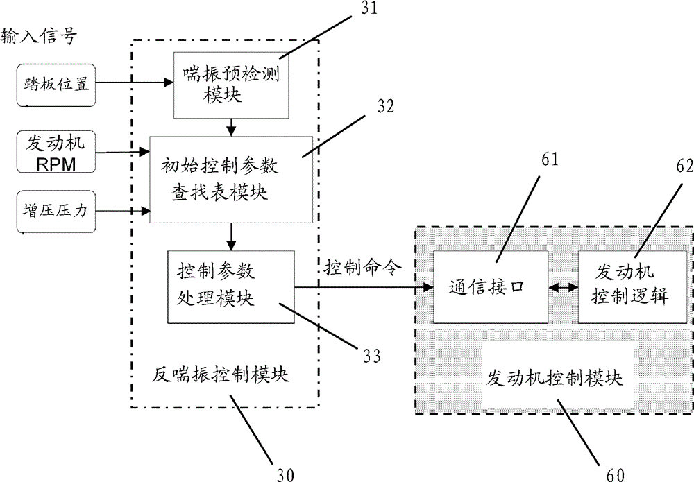
The present invention provides an engine control method, which comprises: receiving an indication of the pedal position; pre-processing the indication of the pedal position to determine whether the received indication of the pedal position corresponds to the antisurge mode activation condition; in response to the received indication of the pedal position corresponding to the antisurge mode activation condition, using the boost pressure and the engine speed to look up the static control parameter lookup table to select a control parameter indicating an air flow requirement; and sending the selected control parameter to the ECU so as to control the engine using the air flow requirement indicated by said control parameter.

Description

technical field [0001] The present invention relates generally to engine control techniques and, more particularly, to methods and systems for providing improved engine control. Background technique [0002] Gasoline or natural gas engines have been the primary mode of propulsion for many types of vehicles for many years. Therefore, aiming to improve the performance of gasoline or natural gas engines in the areas of power and efficiency is a desirable goal. A turbocharger is an example of improving the performance of a gasoline or natural gas engine. A turbocharger can be thought of as a type of gas compressor used to increase the mass of air entering the engine to produce more engine power. Therefore, a turbocharger is an air compressor driven by the exhaust gas generated by the operation of the internal combustion engine, which can increase the air flow into the internal combustion engine or boiler, thereby improving the efficiency of the machine. Commonly used in autom...

Claims


Application Information

Patent Timeline
Patent Type & Authority Applications(China)
IPC IPC(8): F02D23/00
CPCF02D41/0007F02D11/02F02D41/28F02D2200/0406F02D2200/101F02D2200/602Y02T10/12
Inventor 邵德志顾茸蕾王小乐P.D.马蒂诺
Owner GARRETT TRANSPORATION I INC
Learn More