
clamping equipment

A clamping device and clamping technology, applied in the field of machine components, which can solve the problems affecting the repeatability of measurement and achieve the effect of high balance quality

Active Publication Date: 2016-10-12
SCHENCK ROTEC GMBH
View PDF8 Cites 0 Cited by
  • Summary
  • Abstract
  • Description
  • Claims
  • Application Information

AI Technical Summary

Problems solved by technology

But the concentricity error caused by this tolerance is reflected in the measurement result and seriously affects the repeatability of the measurement

Method used


Image

  • clamping equipment

Examples


Embodiment Construction

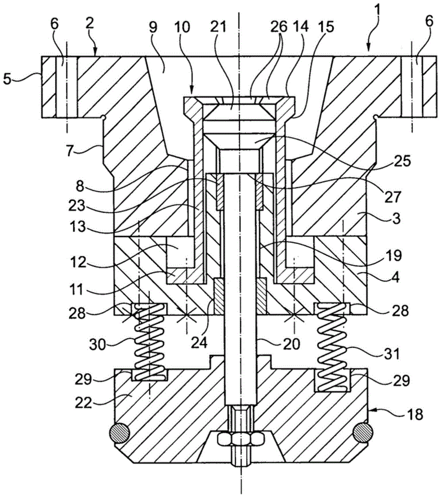
[0018] The shown clamping device 1 is positively inserted into the open end of the hollow spindle of the balancing machine for this purpose. The clamping device 1 has a receiving unit 2 consisting of two parts connected to each other by a screw connection, a receiving part 3 and a bearing part 4 . The flange 5 with fastening bores 6 on the receiving part 3 is used to fasten the receiving unit 2 on the end face of the hollow spindle. For precise centering relative to the hollow spindle, the receiving part 3 is provided with a centering surface 7 on its outer side. A through-hole 8 extends axially through the receptacle 3 , which leads to a central receptacle opening 9 which is designed to receive a standardized hollow bevel-cone coupling shaft of a tool. It is of course also possible to form the receptacle 3 which also has a differently designed receptacle opening for receiving a differently shaped clutch shaft.

[0019] In the through-opening 8 there is a clamping jaw 10 , w...


PUM


Abstract

a receiver unit (2) having a receiving opening (9) for the coupling shaft of the toolholder and a collet (10), in which the shaft (20) of an actuator (18) for actuation of the collet (10) is slidably guided in a centrally located bore (19) of the receiver unit (2). The shaft (20) has at its one end a load-applying body (22) upon which a plurality of compression springs (30, 31) take support to enable the collet (10) to be tightened. The compression springs (30, 31) are arranged and / or configured in such a way that the spring loads acting on the load-applying body (22) with the collet (10) tightened act on the load-applying body (22) asymmetrically relative to the axis of the shaft (20).

Description

technical field [0001] The invention relates to a clamping device for clamping in a balancing machine a machine part defined to rotate about an axis of rotation, in particular a tool holder of a drilling, milling or grinding tool. Background technique [0002] Clamping devices of the above-mentioned type are mainly used in balancing machines for clamping tools that can be driven in rotation at high rotational speeds. High demands are placed on the balancing of such tools, since an insufficiently balanced tool impairs the machining quality. In order to be able to meet the high demands on the balancing quality, precise centering of the tool to be balanced requires the aid of a clamping device arranged on the spindle of the balancing machine. [0003] A clamping device for clamping a tool holder provided in a balancing machine is known from WO 00 / 45983 A1, wherein a base unit fixed on a machine spindle driven in rotation about an axis of rotation has a central A receiving ope...

Claims


Application Information

Patent Timeline
Patent Type & Authority Patents(China)
IPC IPC(8): B23B31/26G01M1/04
Inventor A.布施贝克M.布莱特威泽D.皮特A.斯托克
Owner SCHENCK ROTEC GMBH
Learn More