Refrigerant compressor and heat pump device

A refrigerant and compressor technology, applied in compressors, refrigerators, compressors, etc., can solve the problem of insufficient return of lubricating oil, and achieve the effect of reducing solubility

Inactive Publication Date: 2015-02-25
MITSUBISHI ELECTRIC CORP
View PDF6 Cites 5 Cited by
  • Summary
  • Abstract
  • Description
  • Claims
  • Application Information

AI Technical Summary

Problems solved by technology

[0006] In addition, there is another problem that if lubricating oil that is incompatible with HC refrigerant is used, the lubricating oil carried out into the refrigeration cycle cannot be sufficiently returned to the compressor.

Method used


Image

  • Refrigerant compressor and heat pump device
  • Refrigerant compressor and heat pump device
  • Refrigerant compressor and heat pump device

Examples


Embodiment approach 1

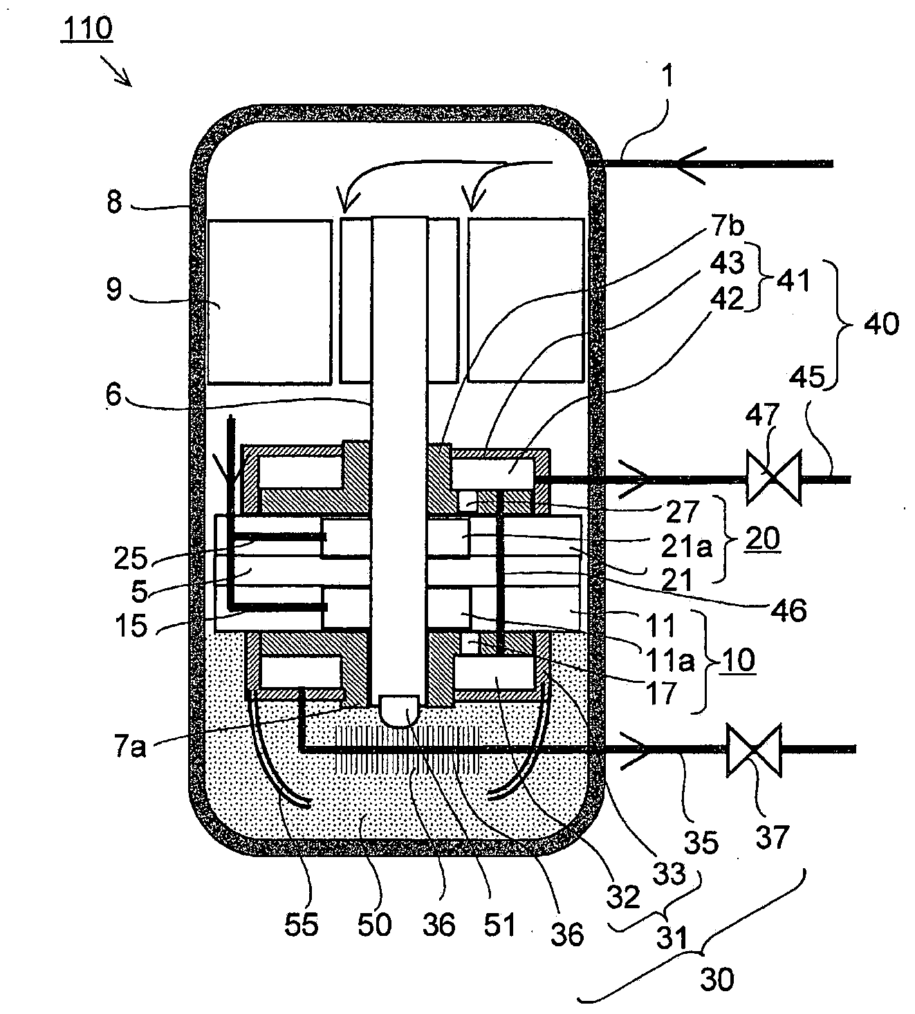
[0067] figure 1 It is a longitudinal sectional view schematically illustrating the refrigerant compressor according to Embodiment 1 of the present invention. In addition, each part is a part drawn schematically, and this invention is not limited to the form shown in figure.

[0068] (Low-pressure shell type 2-cylinder compressor)

[0069] exist figure 1 Among them, the refrigerant compressor (hereinafter referred to as "low-pressure shell-type 2-cylinder compressor" or "refrigerant compressor") 110 has an airtight container 8, an electric motor 9 installed in the airtight container 8, and a drive shaft driven by the electric motor 9. 6. The short-axis side bearing 7a and the long-axis side bearing 7b supporting both ends of the drive shaft 6, the first (lower side) compression mechanism 10 composed of the first (lower side) cylinder 11, and the second (lower side) compression mechanism 10 formed by the second (lower side) The second (upper) compression mechanism 20 constitu...

Embodiment approach 2

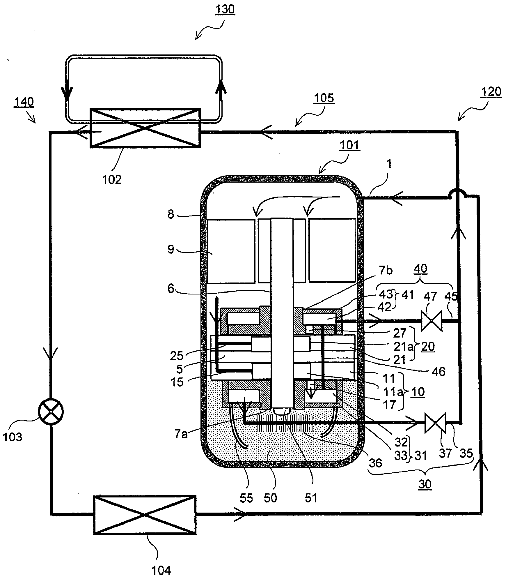
[0084] figure 2 It is a configuration diagram schematically illustrating a partial longitudinal section of a heat pump device according to Embodiment 2 of the present invention. In addition, the same parts as those in Embodiment 1 are assigned the same reference numerals, and a part of description is omitted. In addition, each part is a part drawn schematically, and this invention is not limited to the form shown in figure.

[0085] (heat pump hot water supply)

[0086] exist figure 2 Among them, a heat pump device (hereinafter referred to as “heat pump water heater”) 140 includes a main refrigerant circuit 120 and a utilization fluid circuit 130 . The main refrigerant circuit 120 implements a refrigeration cycle through a refrigerant compressor 110 , a radiator 102 , an expansion valve 103 , an evaporator 104 , and refrigerant piping 105 sequentially connecting them to circulate the refrigerant.

[0087]Here, the refrigerant compressor 110 is the low-pressure shell type...

Embodiment approach 3

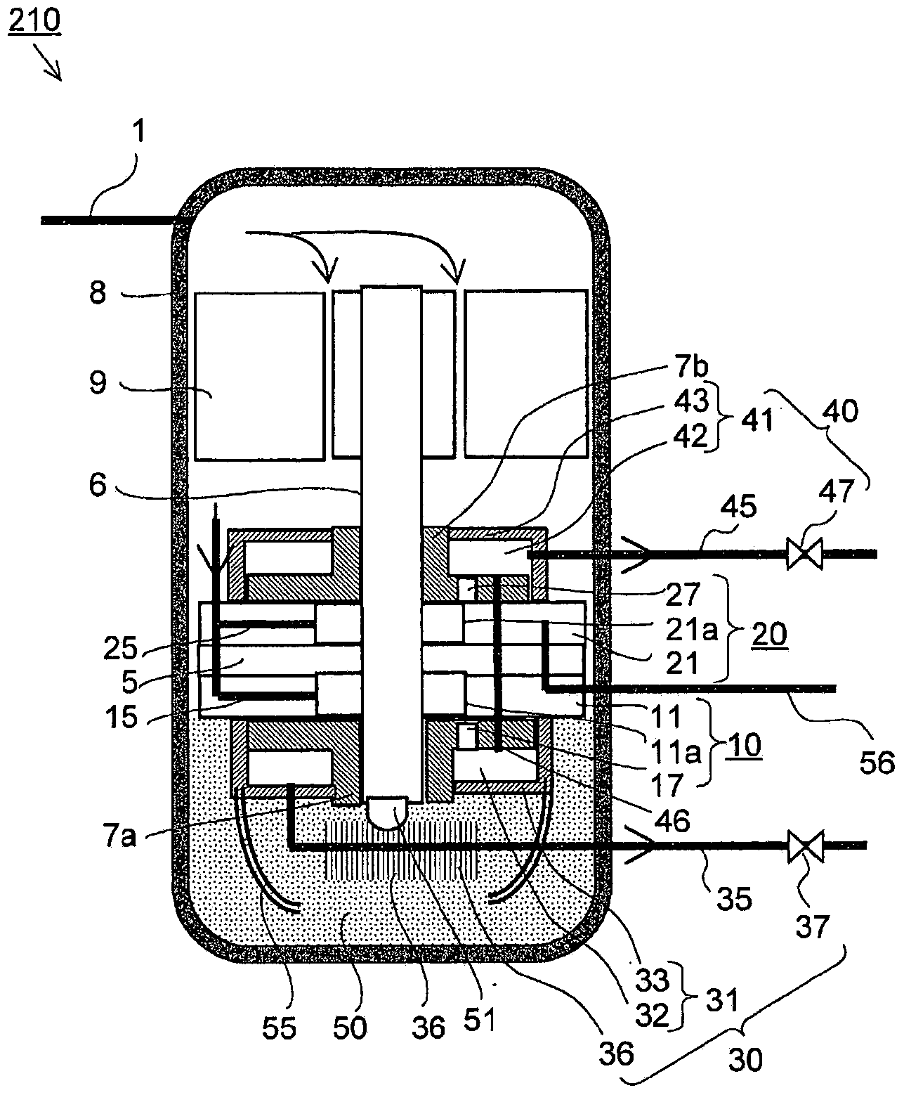
[0095] image 3 It is a longitudinal section schematically illustrating the refrigerant compressor according to Embodiment 3 of the present invention. In addition, the same parts as those in Embodiment 1 are assigned the same reference numerals, and a part of description is omitted. In addition, each part is a part drawn schematically, and this invention is not limited to the form shown in figure.

[0096] (Low-pressure shell type 2-cylinder compressor)

[0097] exist image 3 Among them, a refrigerant compressor (hereinafter referred to as “low pressure shell type 2-cylinder compressor”) 210 is provided with an oil return circuit 56 . The oil return circuit 56 is used to transfer the refrigerant flowing out from one or both of the first (lower) discharge flow path 35 and the second (upper side) discharge flow path 45 in a refrigerant circuit (not shown). After the oil is separated, the separated oil is returned to the first (lower) compression mechanism 10 and the second ...


PUM


Abstract

This refrigerant compressor (110) comprises an airtight container (8), a compression mechanism (3) accommodated in the airtight container (8) and used for drawing in and compressing refrigerant, an electric motor (9) accommodated in the airtight container (8) and used for driving the compression mechanism (3), and an oil storage part (50) formed in the bottom part of the airtight container (8) and used for storing lubricating oil; the interior of the airtight container (8) being an atmosphere of refrigerant intake pressure, and the interior of the airtight shell being provided with a heat exchange means for heating using high-pressure refrigerant immediately after the lubricating oil stored in the oil storage part (50) has been discharged from the compression mechanism (3).

Description

technical field [0001] The present invention relates to a refrigerant compressor and a heat pump device, and more particularly to a refrigerant compressor used in a heat pump device such as a freezer, an air conditioner, or a hot water supplier, and a heat pump device using the compressor. Background technique [0002] In recent years, in refrigerant compressors, from the viewpoint of preventing global warming, technologies to reduce the amount of Freon refrigerants used, and technologies to use flammable refrigerants with zero ozone layer destruction coefficient and low global warming coefficient are required. technology. [0003] In particular, hydrocarbon refrigerants (hereinafter referred to as "HC refrigerants") having excellent refrigerant properties are expected. HC refrigerants have the same refrigerant properties as Freon refrigerants in terms of sliding part lubrication performance, leakage sealing performance, and theoretical COP. Refrigerators using isobutane ha...

Claims


Application Information

Patent Timeline
Patent Type & Authority Applications(China)
IPC IPC(8): F25B1/00
CPCF25B31/004F04C23/008F04C29/04F25B2400/05F04C23/001F04C2240/809F25B2500/16F04B39/04F25B1/00F25B2500/12
Inventor 横山哲英关屋慎佐佐木圭河村雷人幸田利秀前山英明加藤太郎
Owner MITSUBISHI ELECTRIC CORP
Why Eureka
Try Eureka