Power conversion device

A technology of power conversion device and converter, which is applied in the direction of output power conversion device, conversion of AC power input to AC power output, conversion of AC power input to DC power output, etc., which can solve the problems of complex structure and high cost of transformers, Achieve high voltage specifications, low cost, and suppress high-order harmonic components

Active Publication Date: 2015-02-25
TOSHIBA MITSUBISHI-ELECTRIC IND SYST CORP
View PDF6 Cites 11 Cited by
  • Summary
  • Abstract
  • Description
  • Claims
  • Application Information

AI Technical Summary

Problems solved by technology

This type of transformer has a complex structure, so there is a problem of large size and high cost

Method used


Image

  • Power conversion device
  • Power conversion device
  • Power conversion device

Examples


Embodiment approach 1

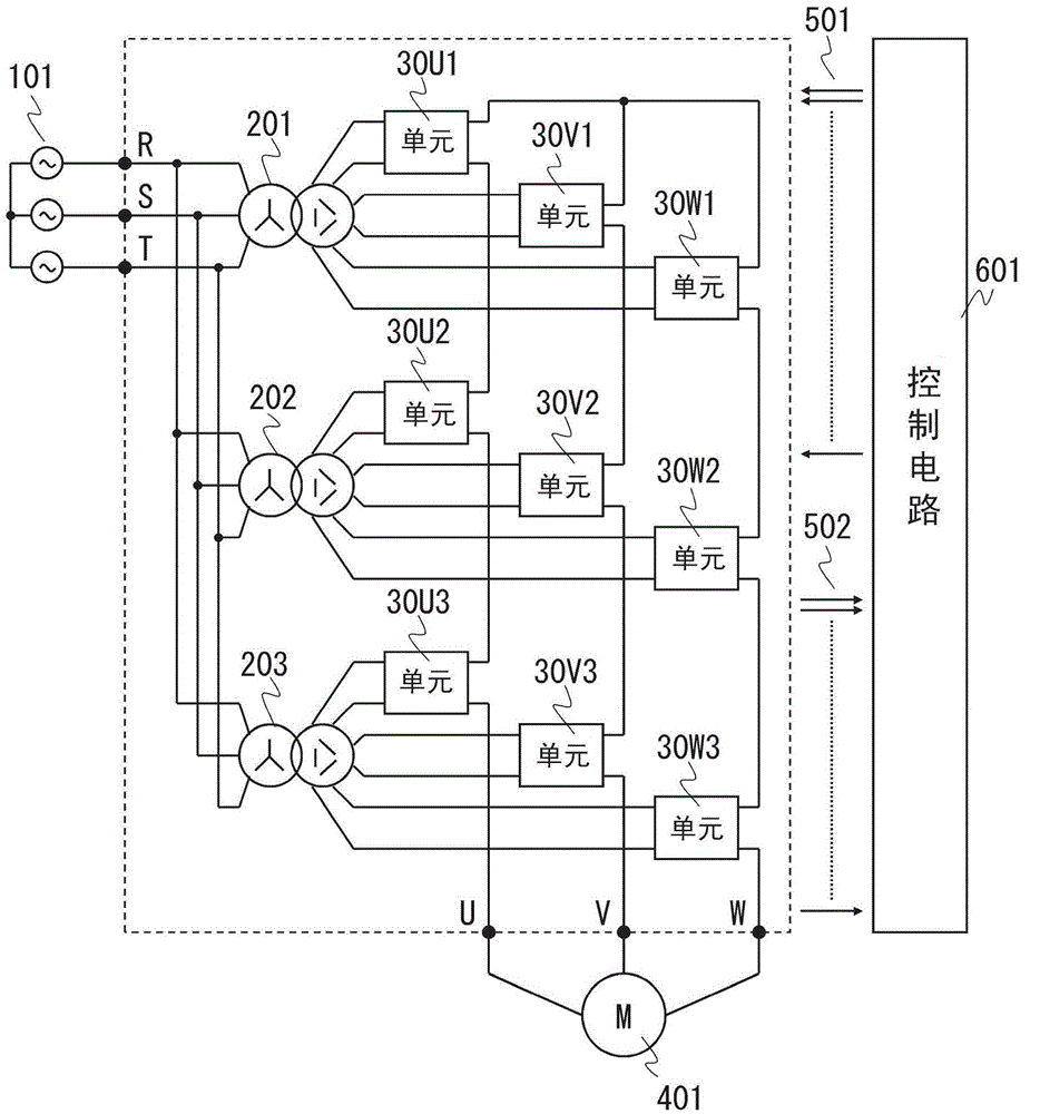
[0041] figure 1 An example of the main circuit configuration of the power conversion device according to Embodiment 1 of the present invention is shown. figure 1 An example is shown in which the input terminals R, S, and T of the power conversion device are connected to the three-phase voltage source 101 , and the output terminals U, V, and W are connected to the three-phase motor 401 . which is, figure 1 An example in which the power conversion device of the present invention is applied as a motor drive device is shown.

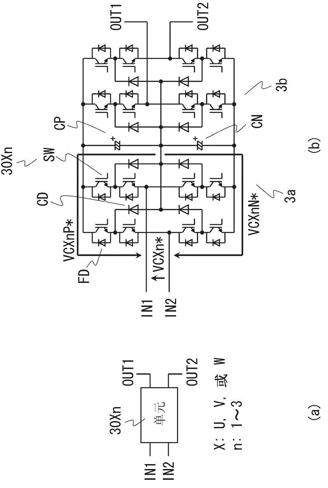
[0042] The main circuit of the power conversion device according to Embodiment 1 of the present invention includes: a transformer device composed of a plurality of transformers 20n (n=1, 2, 3, . . . ), and a plurality of converter units 30Xn (X=U, V , W, ..., n=1, 2, 3, ...). In the present invention, the multi-phase alternating current applied to the input terminal and the output terminal is not limited to three-phase. The invention of the present ap...

Embodiment approach 2

[0109] Figure 15 An example of a main circuit configuration of a power conversion device according to Embodiment 2 of the present invention is shown. Figure 15 Among them, the transformer device is the same as that of Embodiment 1 above figure 1 The transformer arrangement shown (transformer 20n) is different.

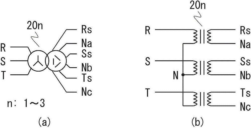
[0110] Figure 16 (a) is a figure which shows an example of the winding structure of the transformer 211 which is the transformer apparatus of this Embodiment 2, and its detailed structure is as follows: Figure 16 (b) shown.

[0111] The primary winding of the transformer 211 is a three-phase star-connected (Y-connected) winding structure as in the first embodiment. Then, the primary winding of one phase is provided with a secondary winding composed of a plurality of (here, three) windings, and the transformers 201 , 202 , and 203 according to Embodiment 1 are assembled into one transformer 211 . As for the secondary winding, each phase has three single-phase ...


PUM


Abstract

A power conversion device includes transformers (20n) provided with primary windings connected to input terminals (R,S,T) and secondary windings including pluralities of single-phase open windings that are insulated from each other; a plurality of converter cells (30Xn) connected to the secondary windings of the transformers (20n); and a control circuit (601) for controlling ON/OFF of switching elements. The converter cells (30Xn) each include a converter (3a) and the inverter (3b) that are provided with the switching elements, in which their input ends are connected to the respective single-phase open windings, so that the input ends are connected in mutually parallel fashion, through the transformers (20n), to the input terminal (R,S,T) of each phase, and in which their output ends are connected in mutually serial fashion to an output terminal (U,V,W) of each phase, to thereby perform three or more-level power conversion.

Description

technical field [0001] The present invention relates to a power conversion device for converting AC power into AC power, for example, to a power conversion device applied to a device for driving an electric motor at a variable speed. Background technique [0002] Figure 17 An example of the circuit configuration of a conventional first power conversion device is shown. Figure 17 The power conversion device of the present invention is intended to output a high-voltage output voltage to a motor connected to an output terminal, and includes a plurality of single-phase converters in which each AC terminal is connected in series. For the purpose of supplying power to the above-mentioned multiple single-phase converters, a plurality of mutually insulated DC power sources are generated by using a transformer with multiple coils and multiple diode rectifiers, and are respectively connected to the DC parts of the above-mentioned single-phase converters. In addition, for the purpose...

Claims


Application Information

Patent Timeline
Patent Type & Authority Applications(China)
IPC IPC(8): H02M5/458H02M7/48
CPCH02M7/48H02M5/458H02M5/4585H02M7/487H02M7/49H02M1/14H02M7/5395H02M1/12H02M1/0095H02M7/4833H02M5/293
Inventor 地道拓志东圣小柳公之中村利孝下村弥寿仁加藤义人
Owner TOSHIBA MITSUBISHI-ELECTRIC IND SYST CORP
Why Eureka
Try Eureka