Colloid mill stator and rotor and colloid mill comprising stator and rotor

A technology for grinding stators and stators, applied in the field of colloid mills, can solve problems such as efficiency to be improved

Active Publication Date: 2015-03-04
SHANDONG DASHAN ROAD & BRIDGE ENG
View PDF7 Cites 10 Cited by
  • Summary
  • Abstract
  • Description
  • Claims
  • Application Information

AI Technical Summary

Problems solved by technology

Compared with the traditional colloid mill, the shear grinding efficiency of this invention has been improved, but its efficiency still needs to be improved

Method used


Image

  • Colloid mill stator and rotor and colloid mill comprising stator and rotor
  • Colloid mill stator and rotor and colloid mill comprising stator and rotor
  • Colloid mill stator and rotor and colloid mill comprising stator and rotor

Examples


Embodiment

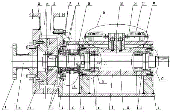
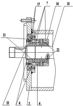
[0032] Such as Figure 1-7 As shown, the colloid mill includes a feed pipe 2, a stator case 3, a casing 5 and a discharge pipe 19, etc., and the left end of the colloid mill is provided with a flange 1 connected to the equipment used in the previous process. A bearing seat 9 is fixedly installed in the box body 5 , and the main shaft 10 is installed in the box body 5 through an angular contact ball bearing 8 (front bearing B) and a deep groove ball bearing 11 (rear bearing C) fixedly arranged on the bearing seat 9 . The main shaft 10 extends through the box body into the working chamber of the stator housing 3 , and the main shaft 10 is fixedly connected to the rotor 18 at the end of the working chamber. The box body 5 is provided with two installation holes of the bearing seat 9, and these two installation holes can ensure that the bearing seat 9 fixed with the main shaft 10 cannot move radially in the holes. The stator 20 is fixedly installed in the working chamber of the s...


PUM


Abstract

The invention discloses a colloid mill stator and rotor and a colloid mill comprising the stator and rotor, and belongs to the field of machinery. According to the colloid mill stator and rotor provided by the invention, the end surface of a stator disc and the end surface of a rotor disc are provided with concentric annular distribution toothed sections; a sluice channel is formed between adjacent toothed sections; straight teeth are arranged on the toothed section at the outermost layer of the end surface of the static disc; trapezoidal teeth are arranged on the toothed sections at the other layers of the end surface of the stator disc; the tooth height of each straight tooth is smaller than the tooth height of each trapezoidal tooth on the end surface of the stator disc; a blind groove is formed in the outer edge of the sluice channel between two adjacent straight teeth; inclined teeth are arranged on the toothed section at the outermost layer of the end surface of the rotor disc; trapezoidal teeth are arranged on the other various layers of the end surface of the rotor disc; the tooth height of each inclined tooth is smaller than the tooth height of each trapezoidal tooth of the end surface of the rotor disc; and a blind groove is formed in the inner edge of the sluice channel between two adjacent inclined teeth. The colloid mill comprising the stator and rotor disclosed by the invention is simple in structure, high in shearing efficiency and long in service life.

Description

technical field [0001] The invention relates to the technical field of mechanical equipment, in particular to a colloid mill stator and rotor and a colloid mill including the stator and rotor. Background technique [0002] The colloid mill includes a casing, a cover, a stator, a rotor, a body, and a main shaft. The stator is fixedly installed in the machine cover, and the rotor is installed on the main shaft in the inner cavity of the casing to cooperate with the stator. The main shaft is installed on the body through a bearing device. The machine body is equipped with a device that cooperates with the main shaft to drive the axial movement of the main shaft to adjust the gap between the rotor and the stator. The main shaft drives the rotor to rotate and cooperates with the stator to grind and stir the medium entering the space between the rotor and the stator, and then discharge it from the outlet on the casing under centrifugal action. The traditional colloid mill stator ...

Claims


Application Information

Patent Timeline
Patent Type & Authority Applications(China)
IPC IPC(8): B02C7/12
Inventor 陈际江隋福云
Owner SHANDONG DASHAN ROAD & BRIDGE ENG
Why Eureka
Try Eureka