Conduit bending molding equipment and conduit bending molding method

A bending forming and catheter technology, which is applied in the structural design and application field of catheter bending and forming equipment, can solve the problems of inability to realize the bending and forming of larger diameter catheters, heavy labor workload, and low productivity, so as to shorten the processing cycle and operation time Effect of shortening and low manufacturing cost

Inactive Publication Date: 2015-03-04
SHENYANG LIMING AERO-ENGINE GROUP CORPORATION
View PDF5 Cites 4 Cited by
  • Summary
  • Abstract
  • Description
  • Claims
  • Application Information

AI Technical Summary

Problems solved by technology

Larger diameter conduits cannot be bent using CNC pipe benders
In actual processing, manual bending is mostly used, and the labor load of workers is large and the productivity is low.
Smaller diameters are okay, but if the batch size is larger or the diameter is thicker, the labor intensity of the workers can be imagined

Method used


Image

  • Conduit bending molding equipment and conduit bending molding method
  • Conduit bending molding equipment and conduit bending molding method
  • Conduit bending molding equipment and conduit bending molding method

Examples


Embodiment 1

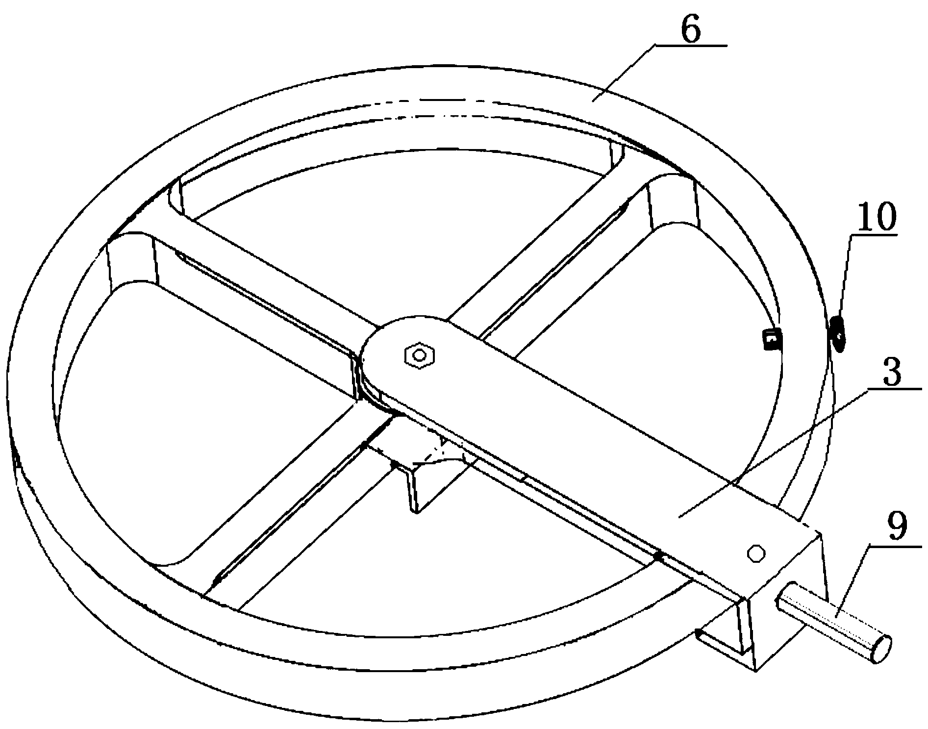
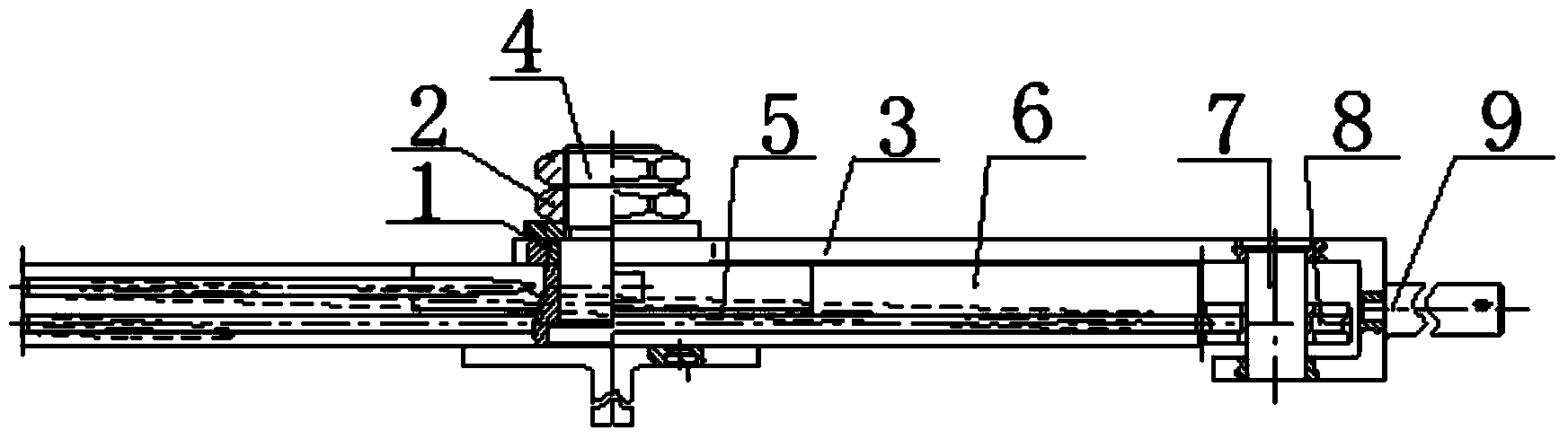
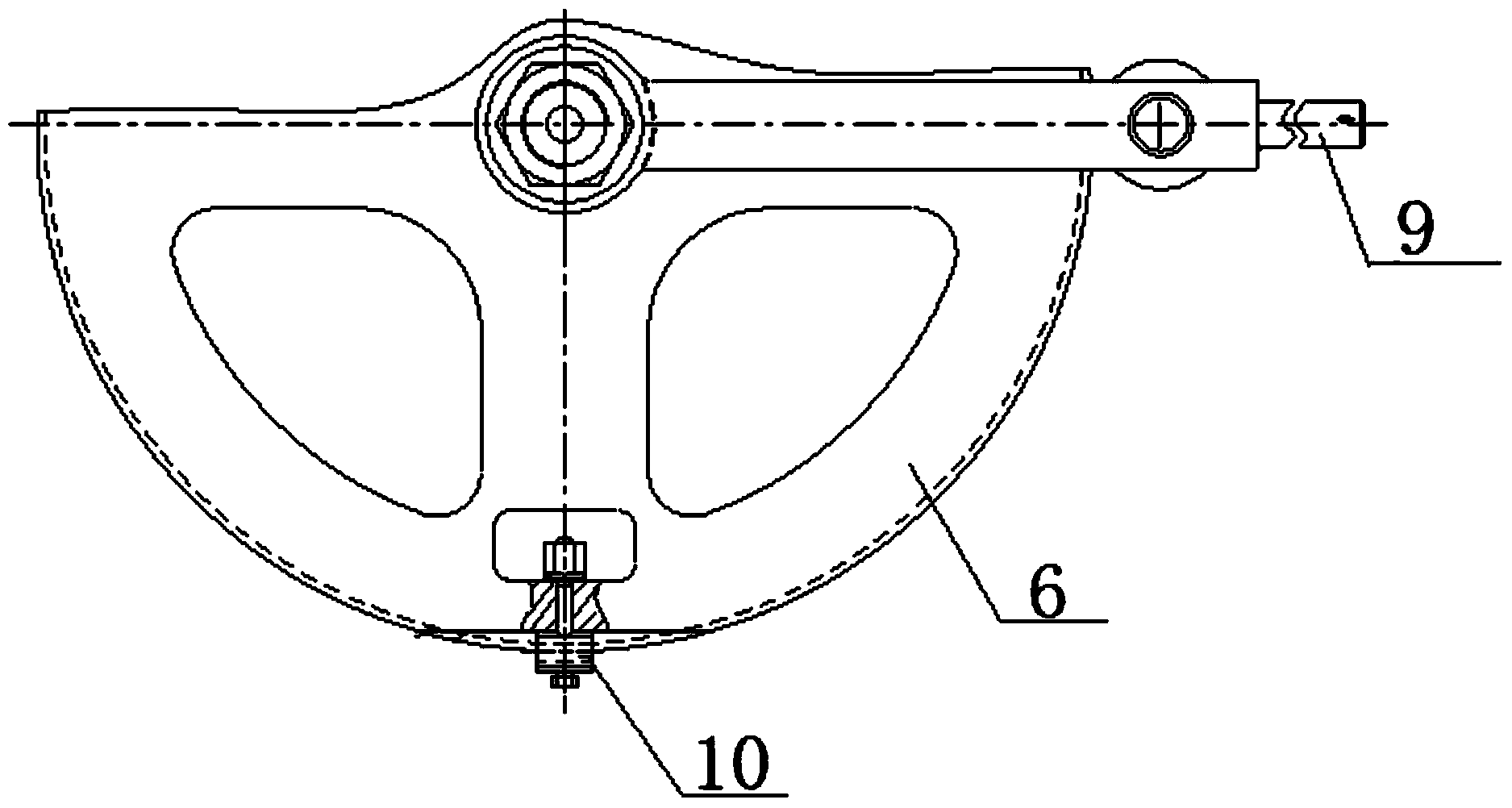
[0025] The catheter bending and forming equipment described in this embodiment is composed as follows: bushing 1, connecting piece 2, rotating arm 3, mandrel 4, fixing seat 5, rotating slide 6, pin 7, roller 8, handle 9, chuck 10; The mandrel 4 is fixed on the fixed seat 5 through the bushing 1 and the connecting piece 2, the rotating slideway 6 is a hollow ring structure, the rotating slideway 6 is sleeved on the mandrel 4 through the bracket, and the chuck 10 is passed through the connecting piece 2 is fixed on the rotating slideway 6, one end of the rotating arm 3 is sleeved on the mandrel 4, and the other end is slidably connected to the outside of the rotating slideway 6 through the pin 7 and the roller 8, and one end of the handle 9 is fixed on the rotating arm 3 .

[0026] The steps of using the catheter bending and forming equipment to bend and shape the catheter are as follows:

[0027] ①Initial pipe inspection: check the type of pipe material, check the outer surfac...

Embodiment 2

[0040] This embodiment is basically the same as Embodiment 1, the difference is:

[0041]The catheter bending and forming equipment described in this embodiment is composed as follows: bushing 1, connecting piece 2, rotating arm 3, mandrel 4, fixing seat 5, rotating slide 6, pin 7, roller 8, handle 9, chuck 10; The mandrel 4 is fixed on the fixed seat 5 through the bushing 1 and the connecting piece 2, the rotating slideway 6 is a hollow ring structure, the rotating slideway 6 is sleeved on the mandrel 4 through the bracket, and the chuck 10 is passed through the connecting piece 2 Fixed on the rotating slideway 6, one end of the rotating arm 3 is sleeved on the mandrel 4, and the other end is slidingly connected to the outside of the rotating slideway 6 through the pin 7 and the roller 8, and one end of the handle 9 is fixed on the rotating arm 3 .

[0042] The steps of using the catheter bending and forming equipment to bend and shape the catheter are as follows:

[0043] ...

Embodiment 3

[0052] The catheter bending and forming equipment described in this embodiment is composed as follows: bushing 1, connecting piece 2, rotating arm 3, mandrel 4, fixing seat 5, rotating slide 6, pin 7, roller 8, handle 9, chuck 10; The mandrel 4 is fixed on the fixed seat 5 through the bushing 1 and the connecting piece 2, the rotating slideway 6 is a hollow ring structure, the rotating slideway 6 is sleeved on the mandrel 4 through the bracket, and the chuck 10 is passed through the connecting piece 2 is fixed on the rotating slideway 6, one end of the rotating arm 3 is sleeved on the mandrel 4, and the other end is slidably connected to the outside of the rotating slideway 6 through the pin 7 and the roller 8, and one end of the handle 9 is fixed on the rotating arm 3 .

[0053] The steps of using the catheter bending and forming equipment to bend and shape the catheter are as follows:

[0054] ①Initial pipe inspection: check the type of pipe material, check the outer surfac...


PUM


Abstract

The invention discloses conduit bending molding equipment and a conduit bending molding method, and aims to realize bending molding of conduits of different pipe diameters ranging from phi4 to phi18. The conduit bending molding equipment consists of a bush (1), a connecting piece (2), a revolving arm (3), a mandrel (4), a fixed seat (5), a rotary slipway (6), a pin (7), a roller (8), a handle (9) and a chuck (10), wherein the mandrel (4) is fixed on the fixed seat (5) through the bush (1) and the connecting piece (2); the rotary slipway (6) is of a hollow annular structure; the rotary slipway (6) is arranged on the mandrel (4) in a sleeving way through a bracket. By adopting the conduit bending molding equipment, the part machining quality is enhanced, and the use requirements in real life are met. Workers are liberated from heavy physical work. Large-diameter turning bending molding of the conduits and deformed steel bars is realized. A pipe bending device is low in manufacturing cost, and is convenient to adjust and use.

Description

technical field [0001] The invention relates to the technical field of structural design and application of conduit bending forming equipment, and in particular provides a conduit bending forming equipment and a conduit bending forming method. Background technique [0002] Catheter refers to a product in the shape of an arbitrary curve in space formed by continuous local plastic deformation of the pipe. Since duct plastic processing can easily meet the requirements of light weight, precision and low consumption of products, it has become an important direction for the development of advanced plastic processing technology. [0003] Catheter bending is one of the more common processing methods. Larger diameter conduits cannot be bent using CNC pipe benders. In actual processing, manual bending is mostly used, and the labor load of workers is large and the productivity is low. Smaller diameters are okay, but if the batch size is larger or the diameter is thicker, the labor i...

Claims


Application Information

Patent Timeline
Patent Type & Authority Applications(China)
IPC IPC(8): B21D7/024B21D7/16
CPCB21D7/024B21D7/16
Inventor 曹勇田海文汪欢周京平徐建辉
Owner SHENYANG LIMING AERO-ENGINE GROUP CORPORATION
Why Eureka
Try Eureka