Rotary type flexible joint

A flexible joint and rotary technology, applied in the field of robots, to achieve the effects of reducing impact, improving service life and high flexibility

Active Publication Date: 2015-03-04
HEBEI UNIV OF TECH
View PDF7 Cites 20 Cited by
  • Summary
  • Abstract
  • Description
  • Claims
  • Application Information

AI Technical Summary

Problems solved by technology

The flexible joint solves the problem that the flexible joint can only produce linear motion, and lays the foundation for designing a joint ro

Method used


Image

  • Rotary type flexible joint
  • Rotary type flexible joint
  • Rotary type flexible joint

Examples


Embodiment Construction

[0015] Further describe the present invention below in conjunction with embodiment and accompanying drawing thereof. However, the protection scope of the claims of the present application is not limited to the description scope of the embodiments.

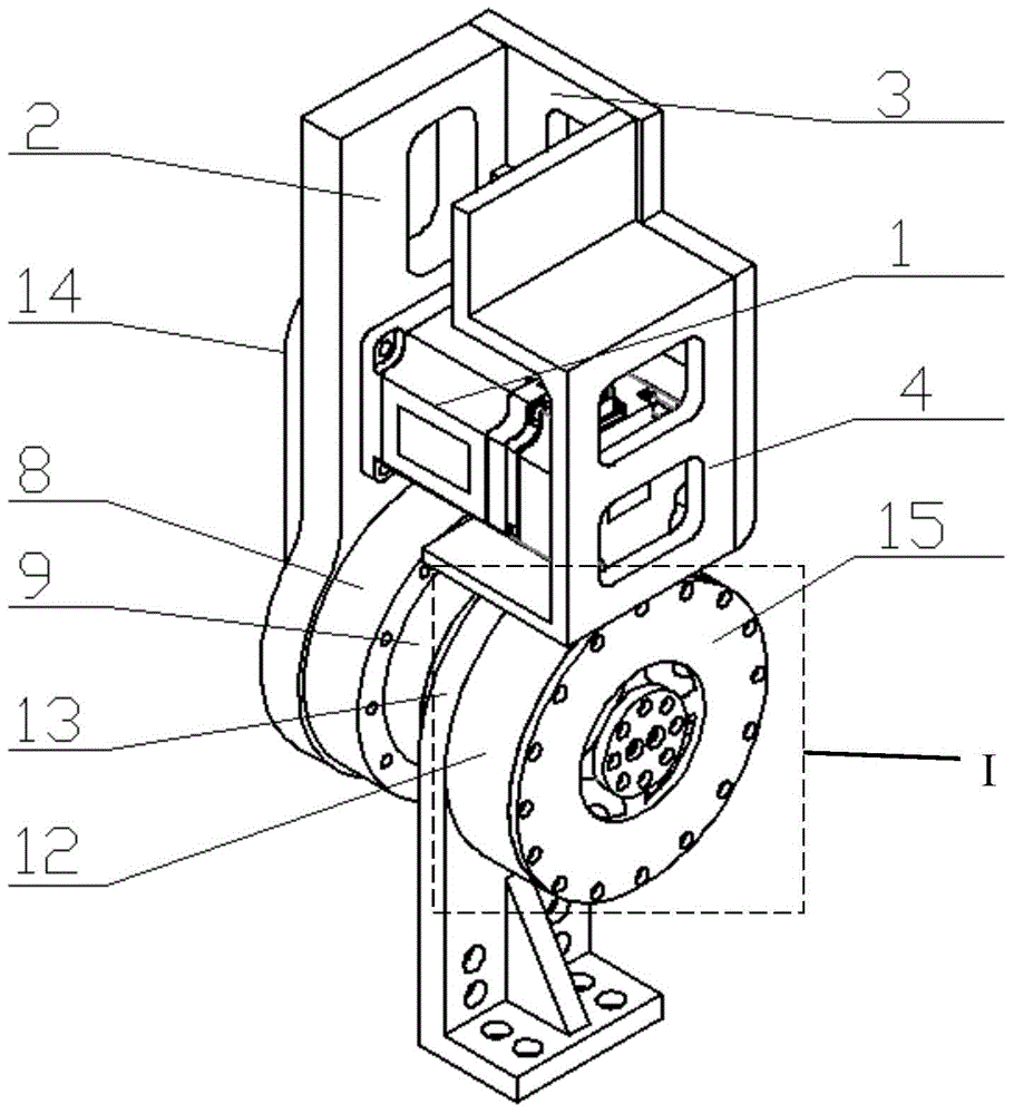
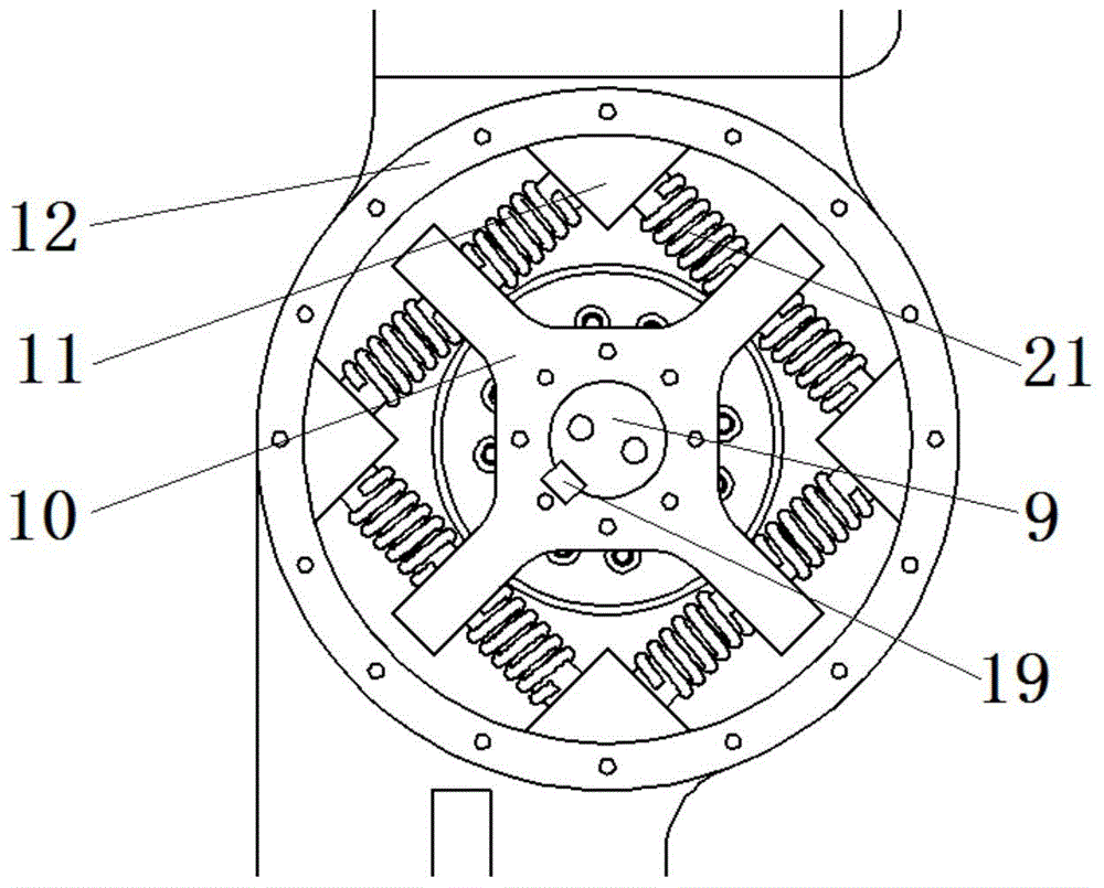
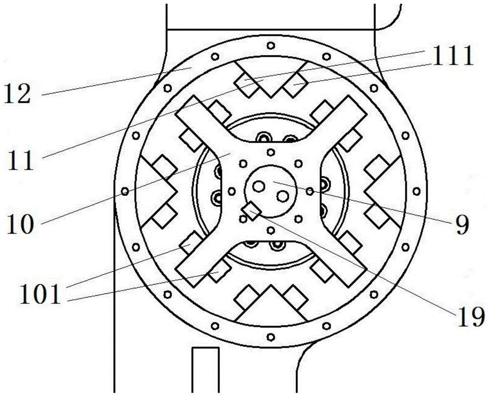
[0016] A rotary flexible joint designed by the present invention (flexible joint for short, see Figure 1-4 ), characterized in that the flexible joint includes a motor 1, a motor frame 2, a mounting plate 3, a first connecting plate 4, a first synchronous pulley 5, a first synchronous pulley cover plate 6, a synchronous belt 7, a reducer 8, Reducer flange 9, spring mounting frame 10, spring output frame 11, output plate 12, second connecting plate 13, synchronous belt end cover 14, third connecting plate 15, cross roller bearing 16, bearing outer ring baffle 17 , Bearing inner ring baffle 18, first flat key 19, reducer flange end cover 20, spring 21, second flat key 22, third flat key 23, second synchronous pulley 24 and second s...


PUM


Abstract

The invention discloses a rotary type flexible joint. The flexible joint comprises a motor, a motor frame, a mounting plate, a first connecting plate, a first synchronous pulley, a first synchronous pulley cover plate, a synchronous belt, a reducer, a reducer flange, a spring mounting rack, a spring output rack, an output disk, a second connecting plate, a synchronous belt end cover, a third connecting plate, a crossed roller bearing, a bearing outer ring baffle, a bearing inner ring baffle, a first flat key, a reducer flange end cover, a spring, a second flat key, a third flat key, a second synchronous pulley and a second synchronous pulley cover plate. The flexible joint solves the problem that the flexible joint only can generate linear motion, and a foundation is laid for designing a joint robot which is high in flexibility, can span certain barriers and pits and has high adaptive capacity to environment.

Description

technical field [0001] The invention relates to robot technology, in particular to a rotary flexible joint. Background technique [0002] With its exploration and work in complex environments, robots have shown strong adaptability, and can replace manpower, improve efficiency, and have begun to be widely used in different fields. As an indispensable part of the robot to complete the movement, the joint is of great significance to the normal work of the robot. The joints of traditional robots are mostly rigid joints, which directly bear the rigid impact during the movement process, resulting in the wear and tear of the joint parts, which directly affects the speed, accuracy and stability of the robot movement; there is still flexibility in contact with the working surface. has many problems. [0003] How to reduce the impulsive force generated by the contact between the robot joint and the working surface during the working process, and reduce the damage of the joint itself...

Claims


Application Information

Patent Timeline
IPC IPC(8): B25J17/00B62D57/02
Inventor 张小俊史延雷梁飞赵慧云张明路
Owner HEBEI UNIV OF TECH
Why Eureka
Try Eureka