
Novel underground controllable casing pipe shaping device

A technology for shaping devices and casings, applied in wellbore/well components, earth-moving drilling and other directions, can solve problems such as economic losses, casualties, environmental pollution, etc., and achieve the effects of improving economic benefits, long service life, and flexible movement

Inactive Publication Date: 2015-03-04
SOUTHWEST PETROLEUM UNIV
View PDF6 Cites 4 Cited by
  • Summary
  • Abstract
  • Description
  • Claims
  • Application Information

AI Technical Summary

Problems solved by technology

[0002] Oil and gas production systems are often in complex working conditions such as high temperature and high pressure, multiple medium environments, and in-situ stress. Such working conditions are bound to cause damage to downhole casings in oil and gas fields. The problem of downhole casing damage in oil and gas fields has always been a problem. One of the serious problems in the development of oil and gas fields, it affects the follow-up operations of oil wells, seriously affects the normal exploitation of oil and natural gas, and sometimes even blowouts and other vicious accidents occur, resulting in major accidents such as casualties, shutdown and production, and environmental pollution, resulting in huge economic loss
Explosive shaping is limited by the external constraints of the casing, and the amount of explosives is difficult to control. Milling shaping weakens the strength of the casing and it is difficult to restore the original diameter. However, expansion shaping is usually prone to jamming after shaping, and traditional shaping techniques are difficult to be effective. Repair damaged bushings

Method used


Image

  • Novel underground controllable casing pipe shaping device
  • Novel underground controllable casing pipe shaping device

Examples


Embodiment Construction

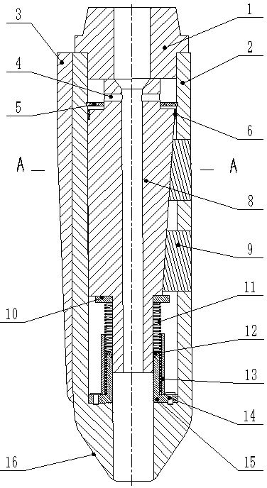
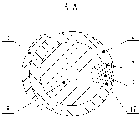
[0012] Depend on figure 1 As shown, a downhole controllable casing shaping device is composed of a casing 2, a body 8, a hard support block 9, a return spring 11, a positioning sleeve 13, and a shaft sleeve 15. It is characterized in that: the connector 1. The upper end is connected to the oil pipe through threads, and the lower end is connected to the casing 2 through threads. There is a shaped prism 3 on one side of the outer surface of the casing 2. The lower end of the casing 2 is a conical guide cone 16; in the inner cavity of the casing, the filter screen 5 is located inside On the upper part of the cavity, a cylindrical body hole 4 is opened on the upper end of the body 8, the body 8 is in clearance fit with the housing 2, and the upper end of the body 8 is equipped with an O-shaped rubber sealing ring 6 radially, and one side of the body 8 has an I-shaped inclined guide rail, hard The support block 9 is installed in the housing hole 7, the housing hole 7 is equipped wi...


PUM


Abstract

The invention provides a shaping device for shaping an oil-gas well casing pipe. The device can realize the shaping of an underground casing pipe, and the service life of the casing pipe can be prolonged. The technical scheme of the shaping device is that the upper end of a connecting head is connected with an oil pipe; a body, a filtering screen, a support plate, a reset spring, a positioning sleeve and a shaft sleeve are sequentially arranged in an inner cavity of a casing from top to bottom; two hard support blocks are arranged in the axial direction of one side of the casing; an I-shaped inclined guide rail is arranged at one side of the body; the hard support blocks can slide on the inclined guide rail; a shaping prism is arranged at one side of the outer part of the casing; and the lower part of the casing is provided with a conical lead cone. During the shaping, the shaping device goes down to a casing pipe deformation position; a pump on the ground holds the pressure; the body is pushed to downwards move through the pressure of workover fluid; the hard support blocks outwards extend out to prop a pipe wall; and the shaping prism realizes the shaping under the rotating effect of the oil pipe. The shaping device has the advantages that the operation is simple; the sealing performance is good; the clamping prevention is realized; the service life is long; the shaping device can be used in repair work of ordinary casing damaged wells; and the utilization rate of an oil-gas well is improved.

Description

technical field [0001] The invention relates to a downhole tool for maintenance of oil wells, a downhole casing shaping device, in particular to a novel downhole controllable casing shaping device with a movable hard support block. Background technique [0002] Oil and gas production systems are often in complex working conditions such as high temperature and high pressure, multiple medium environments, and in-situ stress. Such working conditions are bound to cause damage to downhole casings in oil and gas fields. The problem of downhole casing damage in oil and gas fields has always been a problem. One of the serious problems in the development of oil and gas fields, it affects the follow-up operations of oil wells, seriously affects the normal exploitation of oil and natural gas, and sometimes even blowouts and other vicious accidents occur, resulting in major accidents such as casualties, shutdown and production, and environmental pollution, resulting in huge economic los...

Claims


Application Information

Patent Timeline
Patent Type & Authority Applications(China)
IPC IPC(8): E21B29/10
CPCE21B29/10
Inventor 郑华林余雄风刘少胡何玉辉
Owner SOUTHWEST PETROLEUM UNIV
Learn More