Plastic rivet

A technology of plastic rivets and nail sleeves, applied in the direction of rivets, screws, threaded fasteners, etc., can solve the problems of plastic parts deformation, inconvenient use, etc., and achieve the effect of not easy to detach, easy to manufacture, and simple structure

Inactive Publication Date: 2015-03-04
张举民
View PDF0 Cites 5 Cited by
  • Summary
  • Abstract
  • Description
  • Claims
  • Application Information

AI Technical Summary

Problems solved by technology

When plastic rivets are used, the plastic is melted to form the cap on the other side through the heat burning of the nail rod, which is very inconvenient to use. When connecting plastic parts with plastic rivets, heat burning can easily lead to deformation of the plastic parts

Method used


Image

  • Plastic rivet
  • Plastic rivet
  • Plastic rivet

Examples


Embodiment Construction

[0009] The present invention will be described in further detail below in conjunction with the accompanying drawings and embodiments.

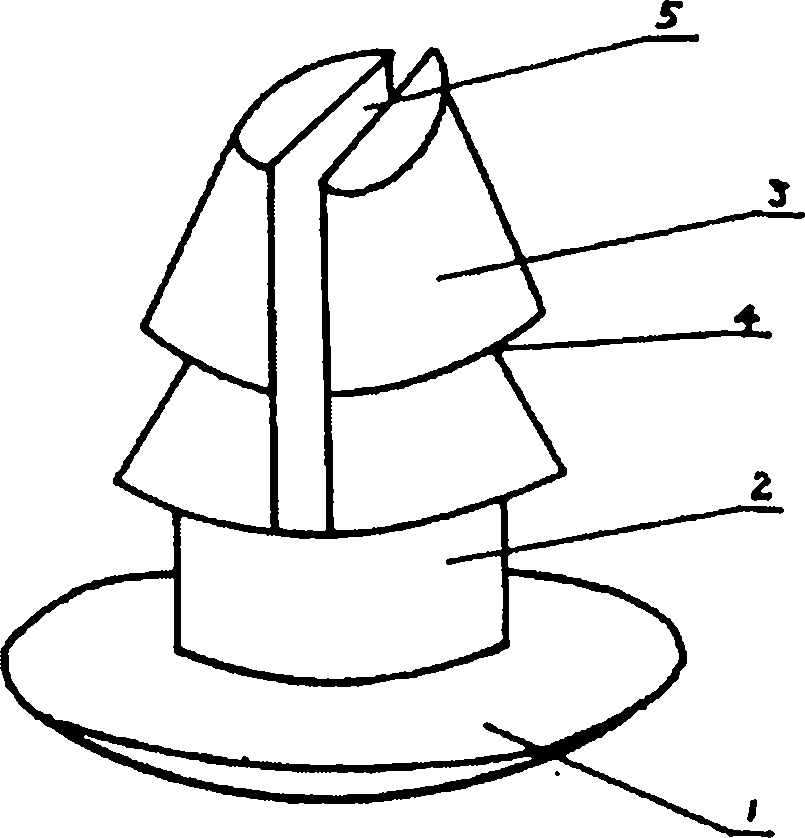
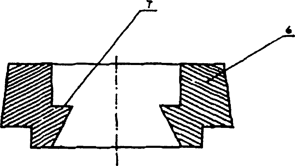
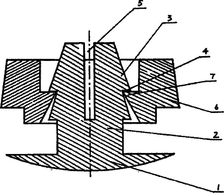
[0010] figure 1 The nail wire has a nail cap 1 and a nail shank 2, two tapered protrusions 3 of the nail shank form an annular depression 4, and a slit 5 is in-line, located in the middle of the nail shank front end, and the slit can also be made into a cross shape. figure 2 There is an annular protrusion 7 on the inner wall of the circular hole in the center of the nail sleeve 6 . When used as image 3 As shown, due to the certain elasticity of the plastic, when the nail rod is pressed into the nail sleeve, the two sides of the slit of the nail rod are compressed toward the middle, and the annular protrusion 7 of the nail sleeve snaps into the annular depression 3 of the nail rod. . Since the nail cap and the nail sleeve maintain a fixed distance, the connected workpieces can maintain a certain degree of looseness, and the workpieces can ...


PUM


Abstract

The invention relates to a plastic rivet. The plastic rivet consists of a screw and a sleeve; the screw comprises a cap and a rod; the rod is provided with at least two conical protrusions; two adjacent conical protrusions form an annular deboss; the front part of the rod is provided with a slit; a round hole in the center of the sleeve is provided with annular protrusions. The plastic rivet is simple in structure and easy to manufacture, and is particularly suitable for connecting a bucket body of a plastic bucket and a sling.

Description

technical field [0001] The invention belongs to connecting parts and relates to a rivet made of plastic material. Background technique [0002] Common rivets include metal rivets and plastic rivets, which are composed of a nail cap and a nail shank, and the nail shank is straight. When plastic rivets are used, the plastic is melted to form the cap on the other side by heating the nail rod, which is very inconvenient to use. When connecting plastic parts with plastic rivets, hot burning is easy to cause deformation of the plastic parts. Contents of the invention [0003] The purpose of the present invention is to provide a plastic rivet that cooperates with each other and can be easily fitted during use. [0004] The present invention is achieved in this way. A plastic rivet is composed of a nail wire and a nail sleeve. The nail wire has a nail cap and a nail shank. There are at least two conical protrusions on the nail shank, and two adjacent conical protrusions form a ri...

Claims


Application Information

Patent Timeline
Patent Type & Authority Applications(China)
IPC IPC(8): F16B19/08
CPCF16B19/083
Inventor 张举民
Owner 张举民
Why Eureka
Try Eureka